
Sensitive RF Voltmeter Probe
The Sensitive RF Voltmeter Probe Circuit is designed to accurately measure RF voltages in the frequency range exceeding 200 MHz, reaching up to approximately 5 volts. This capability makes it suitable for applications in RF testing, telecommunications, and various electronic circuit evaluations where high-frequency signals are present.
The circuit consists of several key components, including resistors, capacitors, and variable resistors (potentiometers), which are essential for setting the appropriate sensitivity and scaling of the voltage measurement. The resistors in the circuit, such as R1 (4.7 MΩ), R2 (1 MΩ), and R3 (1 MΩ), are utilized to create a voltage divider, allowing the circuit to handle high input voltages while providing a manageable output voltage for further processing or display.
Capacitors C1 and C2 (both 0.001 µF disc ceramic) serve as coupling capacitors, blocking any DC component while allowing the AC RF signals to pass through. This ensures that only the RF voltage measurements are considered, eliminating potential interference from DC bias levels. Additionally, C3 (0.1 µF) may be used for filtering purposes, stabilizing the circuit against high-frequency noise.
Variable resistors VR1 and VR2 (both 2 kΩ) are included to allow for calibration and adjustment of the circuit's response, enabling the user to fine-tune the sensitivity based on the specific application or measurement requirements.
The diode D1, likely a 1N series diode, may be employed for rectification purposes, converting the AC RF voltage into a DC voltage that can be measured more easily. This conversion is crucial for displaying the voltage on a standard multimeter or analog meter.
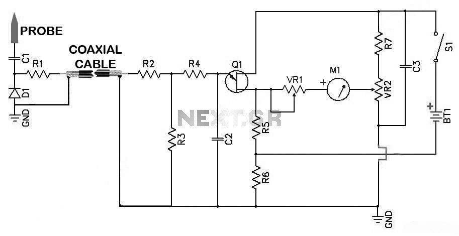
Overall, the design of the Sensitive RF Voltmeter Probe Circuit emphasizes precision in measuring high-frequency signals while maintaining ease of use through adjustable components. This circuit is an invaluable tool for engineers and technicians working in RF applications, providing reliable measurements in a compact and efficient manner.Sensitive RF Voltmeter Probe Circuit This Circuit measures RF voltages beyond 200MHz and up to about 5V. PARTS LISTR14.7M?R21M?R31M?R4100k?R5330?R610k?R710k?VR12k?VR22k?C10.001µF (Disc Ceramic)C20.001µF(Disc Ceramic)C30.01µFD11N..
🔗 External reference
Related Circuits

This document presents a set of plans for constructing an affordable, high-performance digital logic probe that can be assembled within a few hours. The design utilizes a plastic ballpoint pen as the chassis, providing a unique and stylish appearance....
A milliamp meter can be used as a volt meter by adding a series resistance. The resistance needed is the full scale voltage reading divided by the full scale current of the meter movement. So, if you have a...
This project is a combination Logic Probe and Logic Pulser. It is capable of testing all sorts of digital and microcomputer projects. You will find it extremely handy when designing a project as the golden rule is to test...
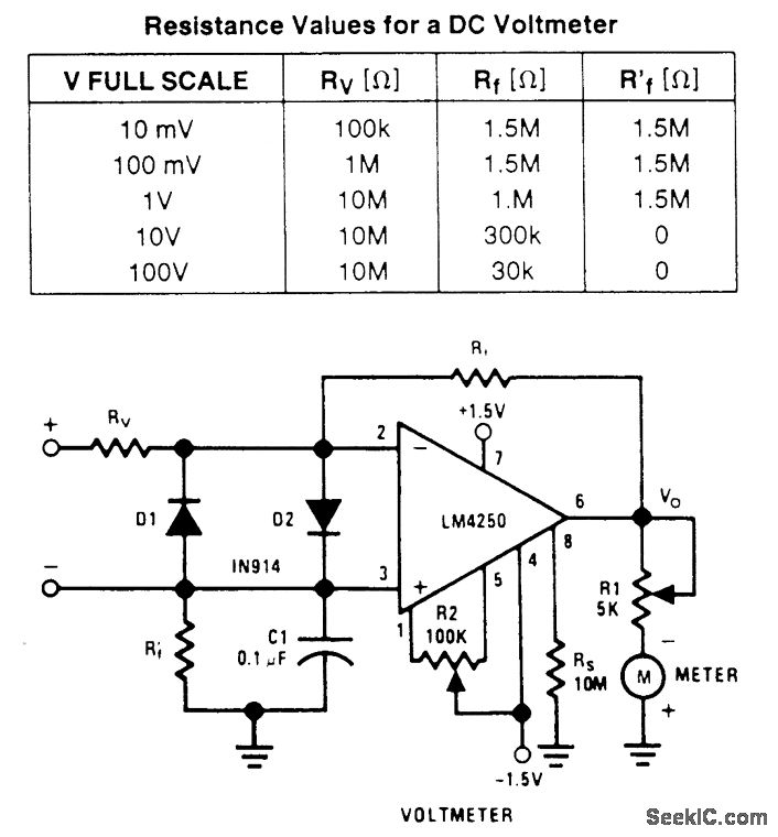
A wide-range voltmeter circuit. This inverting amplifier has a gain varying from -30 for the 10-mV full-scale range to -0.003 for the 100-V full-scale range. Diodes D1 and D2 provide complete amplifier protection for input overvoltages as high as...
A high-input-resistance op-amp, a bridge rectifier, a microammeter, and a few other discrete components are all that are required to realise this versatile circuit. This circuit can be used for measurement of dc, ac rms, ac peak, or ac...
In some cases, a differential input is needed for voltage measurement. By using a single operational amplifier, it is possible to construct an adapter that provides a floating voltage reference. To achieve a differential input for voltage measurement using an...