
Power LED mood Lamp
- 3 x NPN transistors capable of driving 500 mA, for example, the BC337
- one PIC 16F628(A) and a programmer
- a small perforated circuit board
- 7 x 10K resistors (1/4W)
- some 1 watt resistors (4.7, 10, and 15 Ohm) and a DIP switch
- a power supply (5 volts, 500 mA)
- Ikea Mylonit lamp or other housing
- silicon paste from your local DIY shop (if you want to use a heatsink)
- one z-power 3 watt RGB LED
- a little heatsink and some cooling paste (if you want to use a heatsink)
The project described involves creating a LED mood lamp utilizing a PIC16F628 microcontroller for color control, alongside a simple transistor-based switching circuit. The circuit design incorporates three NPN transistors, such as the BC337, which are capable of handling a maximum current of 500 mA, ensuring adequate power management for the RGB LED. The use of a 5V power supply rated at 500 mA is appropriate for this application, considering the maximum current draw of 232 mA when all colors are activated simultaneously.
The programming of the PIC16F628 microcontroller is facilitated by a straightforward PIC programmer and software called ic-prog, where the user uploads a .hex file to configure the microcontroller's operation. Special attention must be given to the configuration of fuse bits to ensure the microcontroller operates correctly in the intended application.
Resistors are utilized in the circuit to limit the current flowing through the LED and transistors, with seven 10K resistors (1/4W) and additional power resistors of 4.7, 10, and 15 Ohms being specified. The inclusion of a DIP switch provides a means of adjusting settings or modes within the circuit.
To physically mount the circuit board, the use of a hot glue gun is recommended to secure the board within the lamp housing, ensuring it remains in place during operation. The project may also benefit from the application of silicon paste and a heatsink to dissipate heat generated by the power components, enhancing the longevity and reliability of the circuit.
Overall, the schematic and components outlined form a cohesive design aimed at creating an aesthetically pleasing and functional LED mood lamp, with flexibility in color output and ease of assembly.A good way to mount the circuit board is to use a hot glue gun to "mold" the circuit underneath the lamp housing. There is plenty of space there for your board. At the next photos you can see the circuit board mounted on the small 31cm IKEA Mylonit Lamp. It's clear that current changes as colors are changing. As you can see the max current needed is 232mA. You should keep in mind that this depends on the led you have and the power resistors you choose. As a conclusion a power supply rated at 5V/500mA will be sufficient. The schematic used is shown in the next image. It's as simple as it shows. Take care on the correct transistor mount and correct polarity of power source. Programming the PIC16F628 can be achieved using this very simple pic programmer and a program called ic-prog. Just use your programmer and upload the .hex file on your PIC. For successful results you should pay attention on the fuse bits. You should enter the correct fuses as noted on the following table. Here is a list of the components i used for making the led mood lamp. - 3 x NPN transistors capable of driving 500 mA, for example the BC337 - one PIC 16F628(A) and a programmer - a small perforated circuit board - 7 x 10K resistors (1/4W) - some 1 watt resistors (4,7, 10 and 15 Ohm) and a DIP switch - a power supply (5 volts, 500 mA) - Ikea Mylonit lamp or other housing - silicon paste from your local DIY shop (if you want to use a heatsink) - one z-power 3 watt rgb led - a little heatsink and some cooling paste (if you want to use a heatsink)
🔗 External reference
Related Circuits
This project has two options. It can be a mains operated project, using a 2155 or 2156 transformer or it can be connected to a plug pack. We recommend it be connected to a 16v AC 1 amp plug...
All electronic systems and equipment, regardless of their size or function, share a common requirement: a power supply unit (PSU) that converts input voltage into suitable voltage levels for their circuits. The most prevalent type of PSU today is...
This is a programmable clock timer circuit that utilizes individual LEDs to signify hours and minutes. Twelve LEDs can be arranged in a circular formation to represent the 12 hours of a clock face, while an additional 12 LEDs...
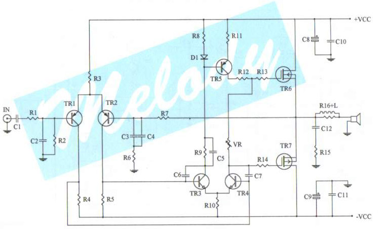
The schematic diagram of a 100-watt audio amplifier utilizing MOSFET technology. A comprehensive collection of electronic circuit diagrams is available, including a 100W RMS amplifier and a 0-30V stabilized variable power supply with current control. The 100-watt audio amplifier schematic...
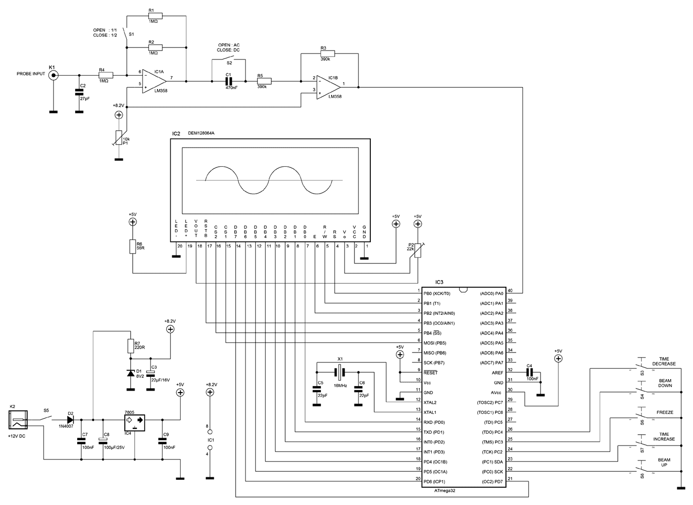
A few months ago as I was surfing on the net, I saw an oscilloscope based on PIC18F2550 microcontroller and a KS0108 controller based graphical LCD. That was Steven Cholewiak's web site. I had never seen before so amazing...
This circuit detects the AC audio voltage supplied to car radio loudspeakers and visually represents it as power using an LED bar graph, creating an appealing visual effect. It is designed to accommodate typical car radio output power ranges...