
Power-On Time Delay Relay With LM339 IC
The thermostat circuit utilizes an LM339 integrated circuit (IC) to manage the operation of a 1300-watt space heater. The LM339 is a quad comparator that can compare voltage levels and provide output signals based on these comparisons. In this application, the circuit is configured to monitor the temperature of the environment and activate or deactivate the heater accordingly.
The circuit typically includes temperature sensors, such as thermistors or thermocouples, which provide a voltage output proportional to the temperature. These sensors are connected to the inputs of the LM339. The reference voltage for the comparators can be set using a voltage divider or a potentiometer, allowing for calibration of the desired temperature threshold.
When the temperature falls below the set point, the output from the LM339 changes state, triggering a control mechanism, often through a relay or a solid-state switch, to turn on the heater. Conversely, when the temperature exceeds the set threshold, the LM339 output will deactivate the heater, ensuring that the space remains within the desired temperature range.
The use of a small pulse transformer in the circuit provides electrical isolation between the control circuit and the high-power heater, enhancing safety and preventing damage to the control components. Additionally, the transformer can help to reduce electromagnetic interference, ensuring stable operation of the thermostat.
Overall, this thermostat circuit efficiently manages the heating process, optimizing energy consumption while maintaining comfort in the controlled environment.The thermostat circuit built to control a 1300 watt space heater which are controlled with a small pulse transformer. Component: LM339 IC, .. 🔗 External reference
Related Circuits
This device is a long-standing controller for various home appliances, including night lights and air conditioners. It is a Miniature Real-time Controller that utilizes three primary components: an 89C2051 microcontroller, a DS275 or MAX232 level shifter, and a 74LS07...
This circuit features an adjustable output timer capable of re-triggering at specified intervals. The output duration can range from a fraction of a second to over half an hour, with the ability to recur at regular intervals spanning from...
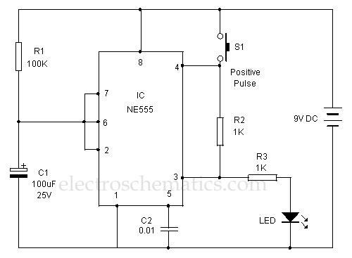
This 555 timer is designed uniquely to provide a positive output through control over its reset pin. Typically, the 555 timer IC is triggered by applying a negative voltage. The 555 timer is a versatile integrated circuit widely used in...
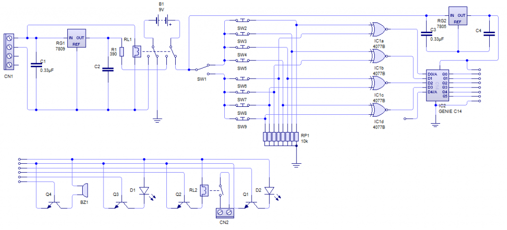
The PC Power-on Combination Lock (PCPCL) was designed for a GCSE Systems & Control project focused on the category of Safety and Security. The aim was to create a product that enhances the security of a desktop PC, addressing...
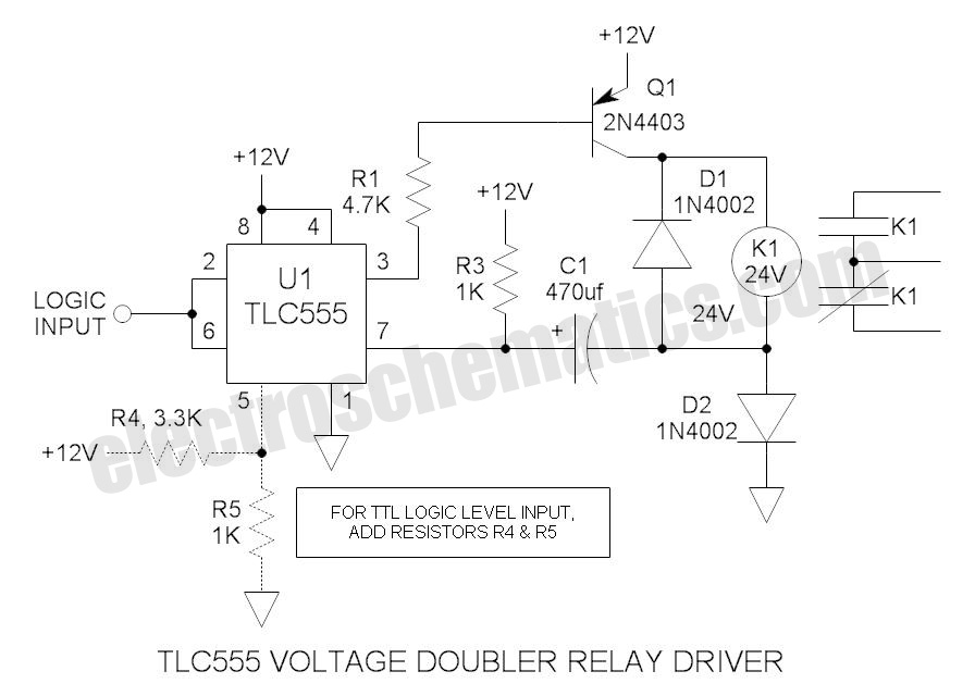
These novel relay driver circuits can activate a relay with a coil voltage rating that is double the Vcc. After activation, the relay armature is held in place. The relay driver circuits described are designed for applications requiring the control...
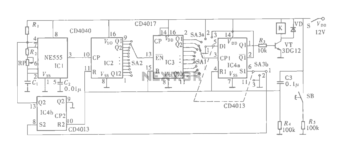
The multifunction circuit primarily refers to its capability to operate in three modes: "delayed pull," "time release," and "delayed cycle." The term "delay" indicates that the relay is energized after a predetermined time; however, the relay does not activate...