
Over-voltage protection circuit
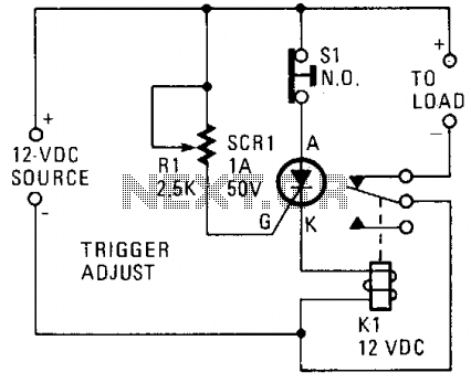
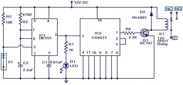
The described circuit employs a silicon-controlled rectifier (SCR) to manage the operation of a relay in response to voltage changes in a 12-V power supply line. The SCR is strategically placed in parallel with the voltage line to monitor the voltage levels effectively. Its gate terminal is connected to a voltage divider or sensing circuit that includes a resistor, R1, which sets the trigger point for the SCR. This configuration ensures that the SCR remains in an off state while the voltage stays below 12 V, thereby maintaining the closed state of relay K1 and enabling current to flow to the connected load.
When the voltage exceeds the predetermined threshold of 12 V, the current flowing through R1 becomes sufficiently high to trigger the SCR. This transition causes the SCR to enter a conductive state, effectively short-circuiting the relay coil and opening the contacts of K1. Consequently, the load is disconnected from the power supply, preventing potential overvoltage conditions that could damage the load.
The choice of R1 is critical as it determines the sensitivity of the SCR to voltage changes. Adjusting R1 allows for fine-tuning the voltage level at which the SCR will trigger, providing flexibility in the circuit's operational parameters. This design is particularly useful in applications where overvoltage protection is needed, ensuring that sensitive devices are safeguarded against voltage spikes.
In summary, this circuit exemplifies a simple yet effective method for controlling power delivery to a load based on voltage levels, using a silicon-controlled rectifier in conjunction with a relay to provide reliable operation and protection.A silicon-controlled rectifier is installed in parallel with the 12-V line and connected to a normally-closed 12-V relay, K1. The SCR's gate circuit is used to sample the applied voltage. As long as the applied voltage stays below a given value, SCR1 remains off and Kl's contacts remain closed, thereby supplying power to the load.
When the source voltage rises above 12 V, sufficient current is applied to the gate of SCR1 to trigger it into conduction. The trigger point of SCR1 is dependent on the setting of R1. Once SCR1 is triggered (activating the relay), K1's contacts open, halting current flow to the load. 🔗 External reference
Related Circuits

A simple frequency meter or frequency counter circuit featuring an LCD display and an AVR microcontroller. This includes a DIY schematic circuit diagram and embedded C code. The frequency meter circuit is designed to measure the frequency of input signals...
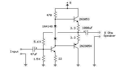
This weblog focuses on electronic circuit schematics, PCB design, DIY kits, and electronic project diagrams. The following describes a small audio amplifier, similar to those found in medium-sized transistor radios. The input stage is biased to ensure equal power...
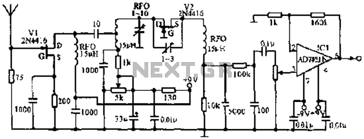
The image illustrates the JFET VHF band super-regenerative receiver circuit. It features high discharge tubes V1 and V2, which serve as the super-regenerative detector tubes. IC1 functions as a low-frequency amplifier. The circuit exhibits a sensitivity of better than...
Incremental rotation or linear encoders are widely used, but they typically do not provide a direction signal. This design presents a straightforward method to detect forward or reverse direction. Incremental encoders usually generate two output signals, referred to as...
This weblog discusses electronic circuit schematics, PCB design, DIY kits, and electronic project diagrams. The circuit diagram presented is for a magnetic proximity switch, which has numerous applications across various fields. The circuit utilizes a magnetic reed switch (S1)...

The ECM circuit comprises four sections, as illustrated in the block diagram. A power converter generates a voltage that correlates with the actual real power consumed by the load. This voltage supplies both a bar graph and a voltage-to-pulse...