
power supply for PC
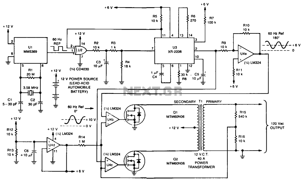
An economical 3.58 MHz color burst crystal provides the time base, which can be precisely adjusted using capacitor C1. The 60 Hz output from U1 is fed into an exclusive-OR gate (U2) and subsequently to the XR-2206 function generator (U3), which converts the square wave into a sine wave. U2 and U3 together create a phase-locked loop that synchronizes the sine wave output of U3 with the 60 Hz square wave reference from U1. The sine wave is inverted by operational amplifier U4a, allowing two signals that are 180 degrees out of phase to be applied to U4b and U4c, which drive Q1 and Q2. In this closed-loop configuration, Q1 and Q2 conduct only during the upper half of the sine wave, with one TMOS device conducting during the first half and the other during the second half.
The UPS circuit design is centered around the efficient conversion and management of power from the battery to the output load. The use of the MTM60N06 Power FETs provides high efficiency and fast switching capabilities, which are essential for minimizing power loss during operation. The center-tapped transformer (T1) plays a crucial role in stepping down the voltage while allowing for the alternation between the two FETs, ensuring that the output is a clean sine wave suitable for sensitive electronics.
The crystal oscillator (U1) is fundamental in maintaining the accuracy of the output frequency, and the ability to adjust the time base using C1 allows for fine-tuning to accommodate variations in load or battery conditions. The phase-locked loop created by U2 and U3 enhances the stability of the output waveform, which is critical for preventing electrical noise that could disrupt the operation of connected devices.
Overall, this UPS design exemplifies a robust approach to providing backup power, with careful consideration given to the synchronization and efficiency of the power conversion process, making it suitable for use with sensitive electronic equipment.The UPS is basically an ac inverter that is powered by a 12-V, lead-acid automobile battery. During power outages, it can supply several minutes of power for an average personal computer. It incorporates a crystal-controlled 60 Hz time base, so that a computer with a real time clock can maintain its accuracy. It isolates the ac line from the computer, so it can be used to operate sensitive electronic equipment on noisy power sources.
Two MTM60N06 Power FETs (Ql and Q2) alternately switch current through a center-tapped 120-V to 12-V filament transformer (Tl) with its primary and secondary reversed. The 120-V output is compared with a 60 Hz reference in a closed-loop configuration that maintains a constant output at optimum efficiency.
A 60 Hz reference frequency is derived from a crystal oscillator and divider circuit, Ul. An inexpensive 3.58 MHz color burst crystal provides the time base that can be accurately adjusted by Cl. The 60 Hz output from Ul is applied to the exclusive-OR gate, U2, and then to the XR-2206 function generator (U3) that converts the square wave into a sine wave.
U2 and U3 form a phase-locked loop that synchronizes the sine wave output of U3 with the 60 Hz square wave reference of Ul. The sine wave is then inverted by op amp U4a, so that two signals 180 out of phase can be applied to U4b and U4c that drive Ql and Q2.
Due to the closed-loop configuration of the drive circuits, Ql and Q2 conduct only during the upper half of the sine wave. Therefore, one TMOS device conducts during the first half of the sine wave and the other conducts during the second half.
🔗 External reference
Related Circuits
When the amplifier is installed inside the suitcase, it will require a change to stop working. The LA47536 has a control pin (pin 4) that requires a small voltage of up to 2V to turn on the amplifier. Transistors...
The following circuit illustrates a power supply for an amplifier circuit diagram. Features include ease of construction and adequate electrical response. The power supply circuit for an amplifier is a crucial component that ensures the amplifier operates effectively. It typically...
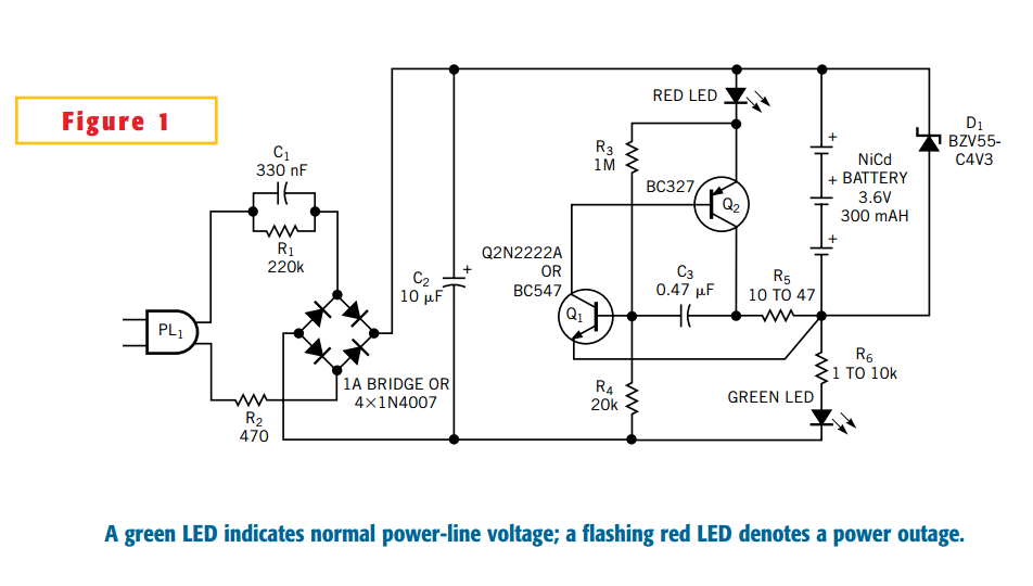
This Design Idea expands on a circuit in a previous one to configure a power-outage detector with a flashing alarm (Figure 1, Reference 1). The circuit plugs into a mains outlet and uses trickle-charged nickel-cadmium batteries. The green-LED monitors...
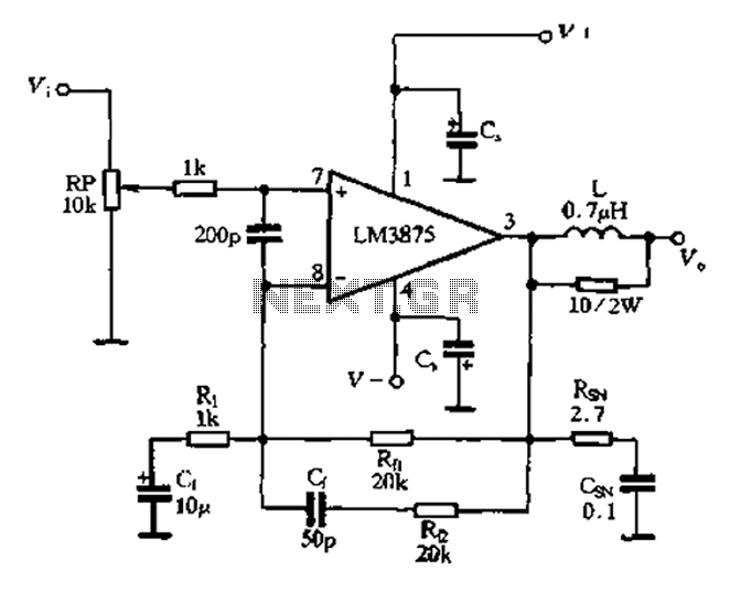
The 875T and LM3876T are high-performance 40W power amplifier integrated circuits (ICs). They operate within a frequency range of 20Hz to 20kHz with a continuous average power output under an 8-ohm load and exhibit a distortion level of only...
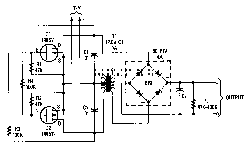
This inverter can deliver high-voltage AC or DC, with a rectifier and filter, up to several hundred volts. The secondary and primary of T1, a 12.6 to 440 V power transformer, respectively, are reversed; e.g., the primary becomes the...
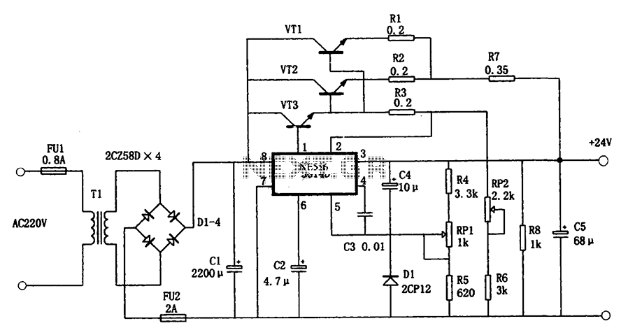
The circuit illustrated in the figure is a +24V, 1.9A power supply design. It employs the 5G14D domestic integrated voltage regulator as the core component, supported by three external power transistors. While the 5G14D voltage regulator has a rated...
Warning: include(partials/cookie-banner.php): Failed to open stream: Permission denied in /var/www/html/nextgr/view-circuit.php on line 713
Warning: include(): Failed opening 'partials/cookie-banner.php' for inclusion (include_path='.:/usr/share/php') in /var/www/html/nextgr/view-circuit.php on line 713