
Synchronization of SMPS Power Modules
The Cyclone V FPGA requires careful consideration of its power supply architecture to ensure optimal performance and reliability. The integration of multiple power modules on a single power board is a practical solution to meet the specific load requirements of the FPGA. This approach allows for the distribution of power across various voltage levels, which is essential for the different operational blocks within the FPGA.
Typically, the power board would incorporate several DC-DC converters, each tailored to supply different voltage rails as dictated by the FPGA's specifications. Common voltage levels required by Cyclone V FPGAs include 1.2V for the core, 2.5V for I/O, and 3.3V for auxiliary functions. The use of synchronous buck converters is recommended for their efficiency in converting higher input voltages down to the required levels with minimal heat generation.
The power management system should also include features such as power sequencing and monitoring to ensure that all voltage rails are stable before the FPGA begins operation. This can be achieved through the use of power management ICs (PMICs) that can coordinate the startup and shutdown sequences of the power modules.
Thermal management must also be considered, as the concentration of multiple power modules can lead to increased heat generation. Adequate heat sinking and airflow must be designed into the PCB layout to maintain operational temperatures within specified limits.
In summary, the effective integration of multiple power modules on a single power board is crucial for meeting the diverse power requirements of Cyclone V FPGAs. This design approach enhances efficiency, reliability, and performance, ensuring that the FPGA operates within its specified parameters.A Practical Application for Cyclone V FPGA Power Requirements The integration of multiple power modules on a single power board allows for specific load requirements to be.. 🔗 External reference
Related Circuits
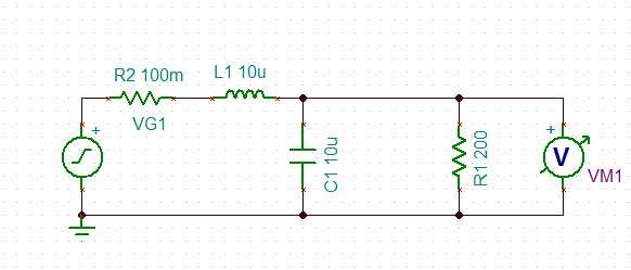
An inductor is used in series with a decoupling capacitor, forming a series LC circuit. One of the characteristics of LC circuits is their resonant frequency. A model of this LC circuit was created with a purely resistive load...
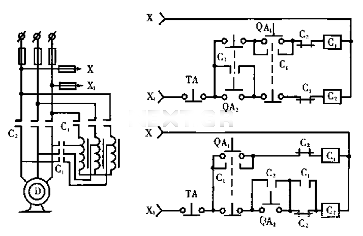
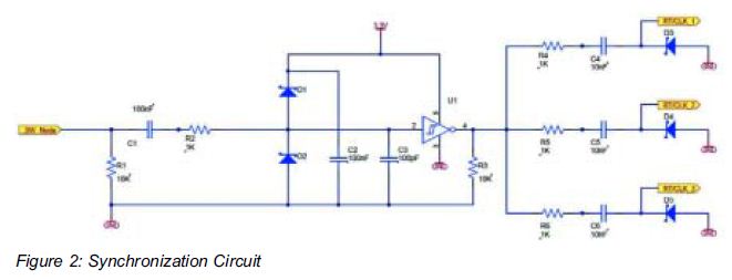
The circuit operates with relevant components highlighted in the manual's draw mode. Figure A presents a circuit schematic, while Figure B illustrates a typical conventional secondary circuit layout. Figure E showcases an improved secondary circuit schematic diagram that incorporates...
The circuit consists of a series of dual power supplies, providing a symmetrical ±15V supply for linear circuits. The same principle is applicable to non-symmetrical supplies, such as 5.0V and -12V regulators, which are used in applications like registers....
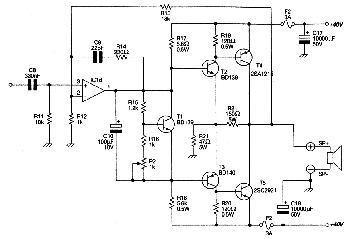
Main Power Amplifier OCL 100 watt using MJ802 and MJ4502 transistors. It is designed to provide strong bass and bold treble, making it suitable for various applications such as parties or home theater systems. This Class AB amplifier delivers...
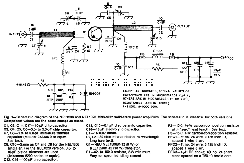
The design incorporates 30-ohm, 1/4 microstrip lines on the input and output. Capacitors C3, C4, C7, and C8, along with inductor L1, form a pi network that matches the low input impedance of the device to 50 ohms. Capacitors...
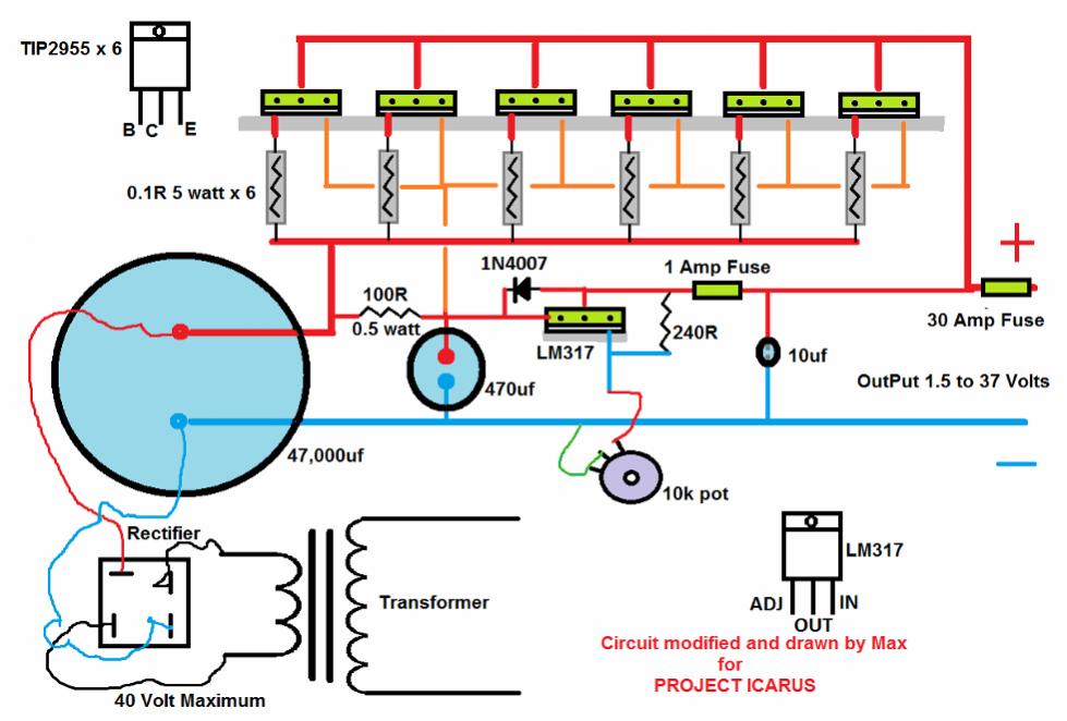
A DC-DC power supply schematic is required that outputs a voltage between 12.7V and 14.5VDC, with an input voltage range from 12VDC upwards. The design of a DC-DC power supply capable of outputting a regulated voltage between 12.7V and 14.5VDC...