
preamplifier
The Hi-Fi stereo preamplifier circuit utilizing the TDA1054 IC is a sophisticated audio amplification solution that provides high-quality sound reproduction. The TDA1054 integrates two preamplifier circuits within a single 16-pin DIL package, making it a compact choice for audio applications. The circuit is designed to operate with a 3 mV input sensitivity, suitable for connecting to phono sources, ensuring compatibility with various audio devices.
The tone control section, which includes capacitors C5 and C3 along with resistors R6 and R8, is crucial for shaping the audio output. This configuration allows for the enhancement of bass frequencies while simultaneously attenuating treble frequencies, enabling users to tailor their listening experience according to personal preferences. The use of switch S1 facilitates easy selection between different input sources, enhancing versatility in audio setups.
The dual potentiometer configuration with P1 and P2 provides fine control over the treble and bass levels, allowing users to adjust the audio output to suit their listening environment. The design ensures that there is no risk of overdrive, which is a common issue in audio circuits, thanks to the passive tone control mechanism. This feature contributes to the overall reliability and sound quality of the preamplifier.
The gain characteristics of the circuit are noteworthy, with both channels achieving a gain of 24 at the midpoint setting of potentiometer P4. This high gain allows for effective amplification of audio signals, ensuring clarity and fidelity. However, it is important to consider that when P4 is adjusted to one extreme, a gain discrepancy of approximately 12 dB may occur between the two channels, which could affect the stereo balance. Overall, this preamplifier circuit is designed to deliver high performance while maintaining ease of use and flexibility in audio applications.This Hi Fi stereo preamplifier circuit is congenital with TDA1054 IC from SGS. TDA1054 is a 16-pin DIL amalgamation and integrates 2 abstracted preamp circuits. It is a low babble preamp with little or no botheration in the building process. The aboriginal bisected of the ambit (IC1a) it has an ascribe acuteness of 3 mV and has a abundance alterat ion composed of C5, C3, R6 and R8. The bass arresting advancing from phono ascribe is amplified while the top arresting is attenuated. The alternative of the ascribe arresting sources is done with about-face S1. P1 and P2 are parte of a bifold potentiometer. They ascendancy the top tones and bass. There is no accident of overdrive in circuit due to the acquiescent attributes of the complete control. Both approach accept a accretion of 24 at the average ambience of P4. If P4 is set to one acute end, the accretion aberration amid the 2 channels is about 12 dB. 🔗 External reference
Related Circuits
Preamps may in some cases use a simple regulator, with the supplies taken from the main amp power supply. This can be a problem if the main amp is of very high power, as the supply voltage will be...
Electronics Circuits Reference Archive Audio preamplifier circuits. There are thousands of preamplifier circuits. Here are three that are somewhat different and have garnered interest. Intercom preamp: A very convenient way of making an intercom system. Audio preamplifiers are essential components...

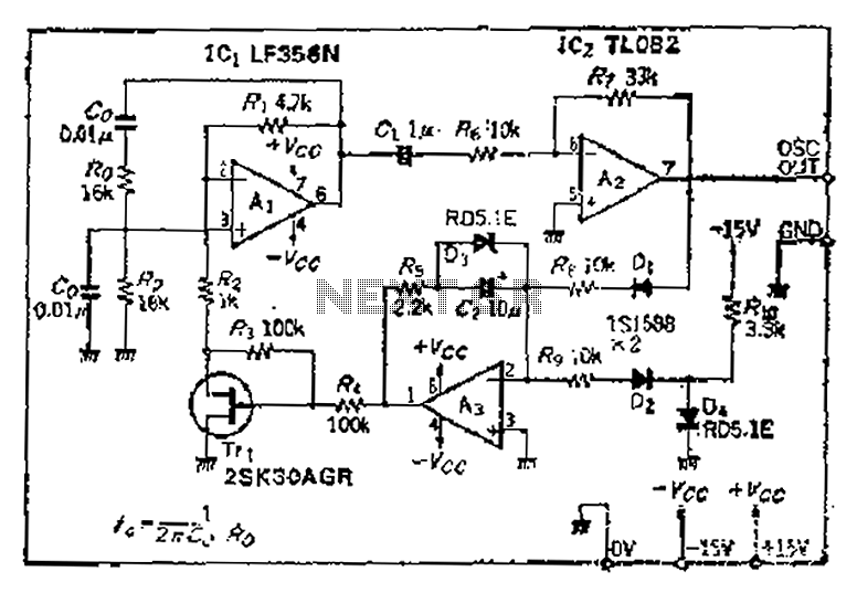
This circuit exhibits an exceptionally fast high-frequency response, as demonstrated by applying a 100 kHz square wave to the input. All graphs were produced using Tina Pro. The circuit's design is optimized for high-frequency applications, showcasing rapid response times that...
This circuit diagram represents an ECM Mic Preamplifier. It is a microphone amplifier compatible with Electret Condenser Microphones (ECM). The preamplifier exhibits an excellent dynamic range, capable of handling audio levels from a whisper to a scream; however, caution...
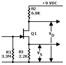
The J201 JFET operates optimally at 10 volts, with a minimum current requirement of 0.5 mA. These specifications are considered ideal, but the actual performance can vary significantly, typically within a range of three to five times. Recent tests...
The intermodal servo preamplifier circuit operates at 115V and 60Hz, designed to provide a differential output for a servo motor amplifier. It features an inverting connection using an operational amplifier (op-amp), along with an additional op-amp configured to create...
Warning: include(partials/cookie-banner.php): Failed to open stream: Permission denied in /var/www/html/nextgr/view-circuit.php on line 713
Warning: include(): Failed opening 'partials/cookie-banner.php' for inclusion (include_path='.:/usr/share/php') in /var/www/html/nextgr/view-circuit.php on line 713