
Precision RTD signal conditioner
This circuit design effectively utilizes the LTC1043 integrated circuit to achieve precise signal conditioning for platinum resistance temperature detectors (RTDs). The simplicity of this configuration, compared to more complex instrumentation amplifiers or multi-amplifier setups, allows for efficient signal processing while maintaining accuracy in temperature measurement applications.
The LTC1043, a precision analog switch, is central to this circuit, enabling the differential sensing of voltage across a feedback resistor of 998 ohms, which is critical for establishing the desired gain and linearity. The operational amplifier A1 functions as a current source, with its output directly influenced by the voltage across the feedback resistor. This feedback mechanism ensures that the output signal remains stable and linear, crucial for applications where temperature accuracy is paramount.
The combination of a 2 kΩ resistor and a 0.1 µF capacitor creates a low-pass filter that effectively rolls off high-frequency noise, ensuring that the operational amplifier's output remains stable and free from unwanted oscillations. This design choice is particularly important in environments where electromagnetic interference may be present.
The fixed voltage across the 887 ohm resistor, maintained by the feedback loop, ensures a constant current through the resistor Rp, which is essential for maintaining the integrity of the signal being processed. The LT1009 voltage reference provides a stable 2.5 V reference point that sets the operating conditions for A1, further enhancing the precision of the circuit.
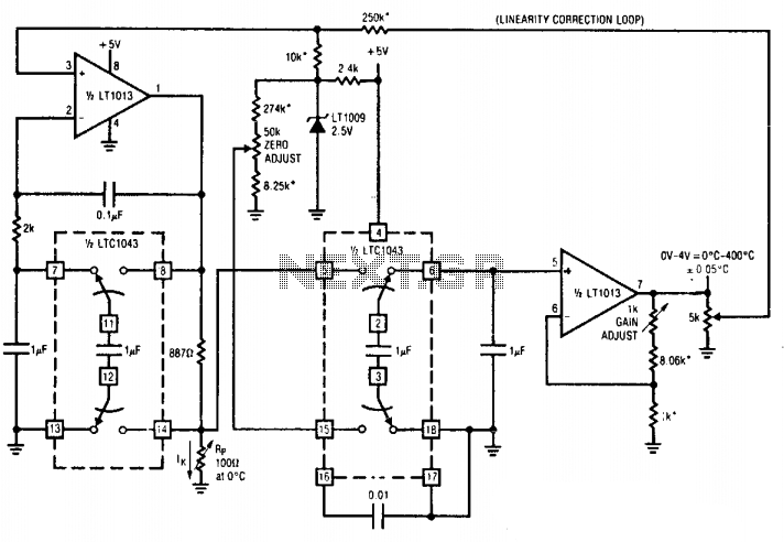
Overall, this circuit design is well-suited for applications requiring accurate temperature measurement and signal conditioning, leveraging the capabilities of the LTC1043 and supporting components to achieve reliable performance.The circuit provides complete, linearized signal conditioning for a platinum RTD. This LTC1043 based circuit is considerably simpler than instrumentation or multi-amplifier based designs, and will operate form a single 5 V supply. Al serves as a voltage-controlled ground referred current source by differentially sensing the voltage across the 998 phm feedback resistor.
The LTC1043 section which does this presents a single-ended signal to Al's negative input, closing a loop. The 2 k 0.1 µ combination sets amplifier roll-off well below the LTC1043's switching frequency and the configuration is stable. Because Al's loop forces a fixed voltage across the 887 ohm resistor, the current through Rp is constant.
Al's operating point is primarily fixed by the 2.5 V LT1009 voltage reference. 🔗 External reference
Related Circuits
This simple circuit generates narrow pulses at about 700-800Hz frequency. The pulses, containing harmonics up to the MHz region, can be injected into audio or radio-frequency stages of amplifiers, receivers and the like for testing purposes. A high-pitched tone...
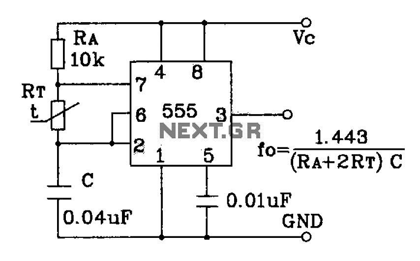
555 precision temperature sensor with temperature frequency converting circuit diagram consisting of: The 555 precision temperature sensor operates by converting temperature variations into frequency signals. This circuit typically utilizes a 555 timer IC configured in astable mode to generate...
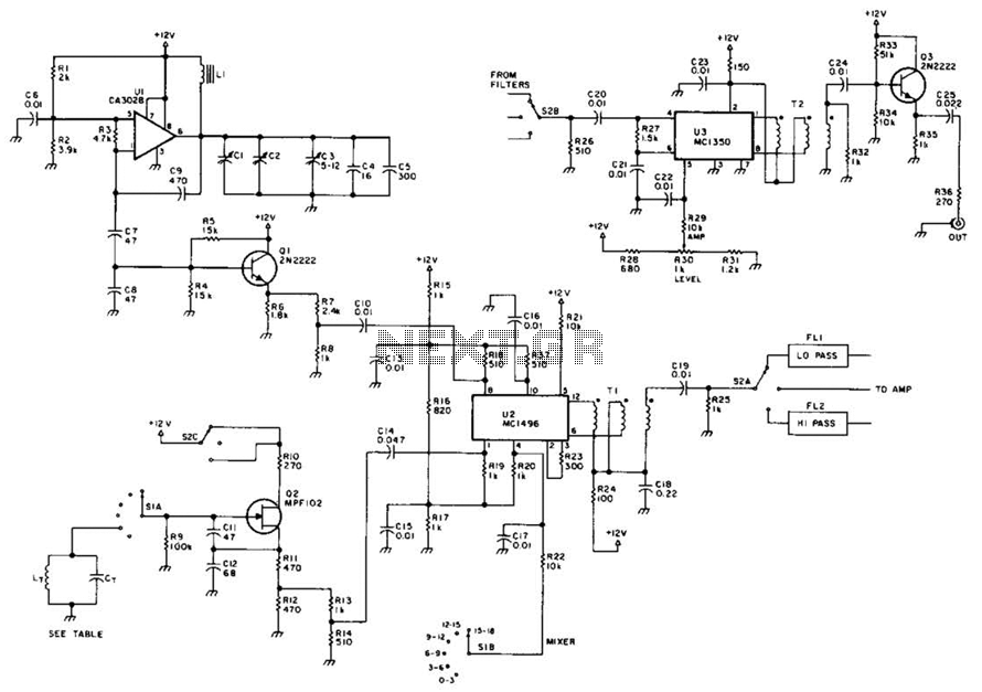
This circuit utilizes a voltage-controlled oscillator (VFO) operating in the frequency range of 15 to 18 MHz (U1), which feeds into a balanced mixer (U2). A fixed oscillator signal is combined with the VFO output to produce an output...
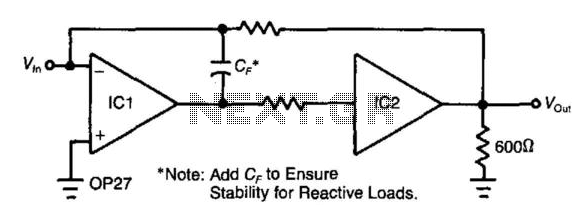
Adding a unity-gain buffer to an analog circuit can enhance its precision. For instance, the operational amplifier IC1 has a maximum offset voltage drift of 1.8 µV/°C and can drive a 600-ohm load. Under these conditions, IC1 would dissipate...
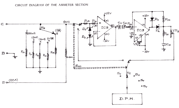
Studying current measurement is essential for various measuring techniques. The current parameter primarily indicates power consumption in a circuit, based on the resistance value. Measuring current is often more convenient than measuring voltage to assess power output and determine...
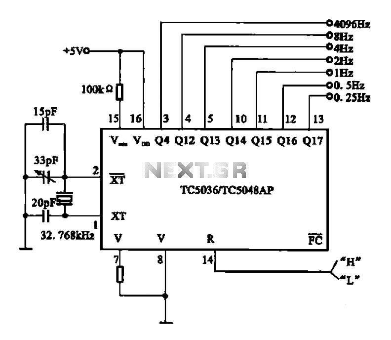
32.768 kHz; In MP3/MP4 devices, mobile phones, laptops, and other digital products, a real-time clock signal generating circuit is utilized, primarily composed of crystal resonators and TC5036/TC5048AP chip oscillators. This setup produces a raw 32.768 kHz crystal oscillator signal,...