
Signal Tracer
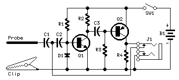
This circuit is designed to generate narrow pulses within the frequency range of 700-800 Hz, making it suitable for various testing applications in audio and radio-frequency domains. The output pulses are rich in harmonics, extending into the MHz range, which allows for effective testing of amplifiers and receivers by injecting these pulses into their respective stages.
The circuit's operation begins with the generation of narrow pulses, which can be achieved using a 555 timer IC configured in astable mode. This configuration allows the timer to continuously oscillate, producing the desired frequency. The output of the timer can be coupled to a transistor stage to amplify the pulses further, ensuring that they can effectively drive the input of the audio or RF stages of the device under test.
To utilize this circuit for testing, a clip is connected to the ground of the device under test. The probe is then used to touch various stages of the circuit, starting from the last stage and moving towards the first. This methodical approach allows for the identification of faulty stages; if the high-pitched tone generated by the circuit is no longer audible, it indicates that the preceding stage is defective.
Additionally, the circuit includes a feature that allows for the connection of an earclip or headphones to the output jack (J1). When connected, the circuit transitions into a two-stage amplifier configuration. This modification enables the circuit to capture any audio signals from the device under test, which can be amplified and heard through the headphones. This capability enhances the utility of the circuit, allowing for both pulse generation and audio signal amplification in a single testing setup.
Overall, this circuit serves as an effective tool for diagnosing faults in audio and RF circuits by providing both a clear indication of operational integrity and the ability to listen to audio signals directly from the device under test.This simple circuit generates narrow pulses at about 700-800Hz frequency. The pulses, containing harmonics up to the MHz region, can be injected into audio or radio-frequency stages of amplifiers, receivers and the like for testing purposes. A high-pitched tone can be heard from the speaker of the device under test when all is working properly.
The clip must be connected to the ground of the device under test, touching with the probe the different stages of the circuit, starting from the last stage and going up towards the first. When the tone is no longer heard, the defective stage has been found. Connecting an earclip or headphone to J1, the circuit will automatically change into a two-stage amplifier and any audio signal coming from the device under test and picked-up by the probe will be heard through the headphones. The testing of a circuit sho 🔗 External reference
Related Circuits
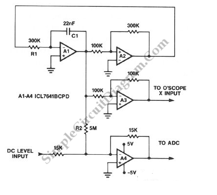
A symmetrical millivolt peak-to-peak triangle waveform can be generated by the circuit illustrated in the schematic diagram below. This circuit is equipped with... This circuit employs an operational amplifier (op-amp) configured in an integrator setup to produce a triangle waveform. The...
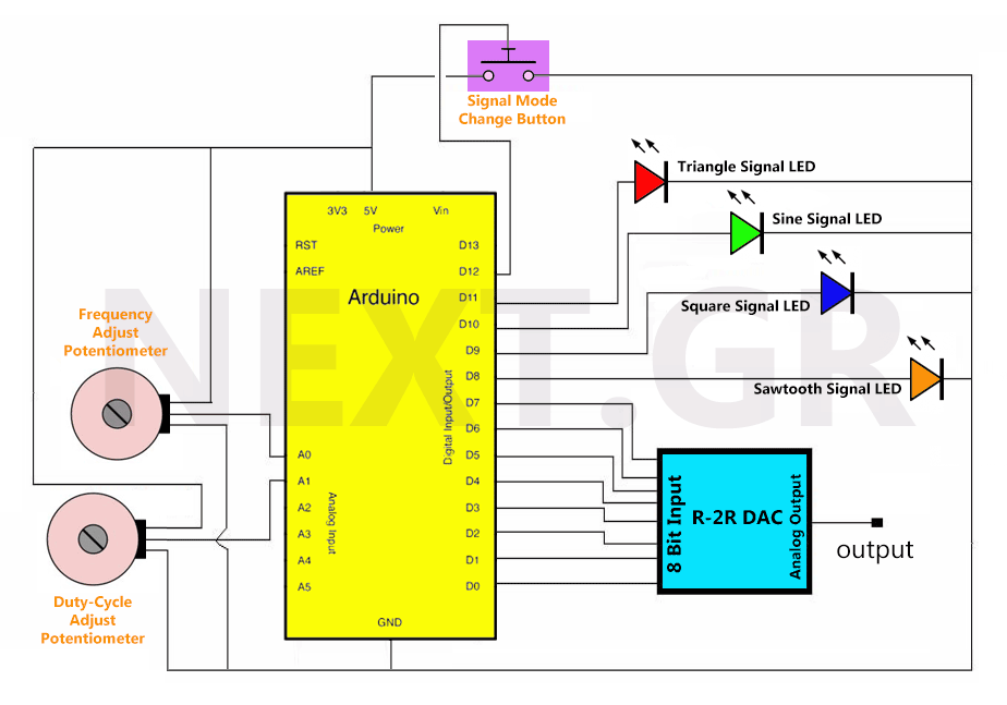
Once the circuit receives power, all variables are initialized, and the loop function runs continuously. Initially, all LEDs are off, and there is no output signal. Pressing the signal switch activates the first LED, indicating the output signal. The...
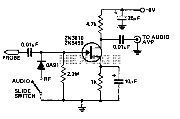
This economical signal tracer is useful for servicing and alignment work in receivers and low power transmitters. When switched to RF, the modulation on any signal is detected by the diode and amplified by the FET. A twin-core shielded...
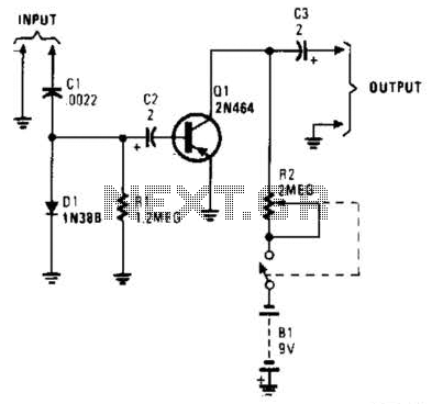
In this circuit, C1, D1, and R1 form an envelope detector. C2 couples audio to the base of Q1. R2 can be adjusted for the desired gain. The circuit under discussion utilizes an envelope detector, which is a fundamental component...
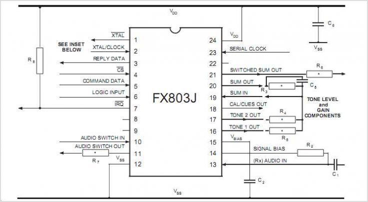
The CMX469A is a single-chip CMOS LSI circuit that functions as a full-duplex modem, supporting baud rates of 1200, 2400, or 4800. The mark and space frequencies for this modem are 1200/1800 Hz, 1200/2400 Hz, and 2400/4800 Hz, respectively....
The STS schematic illustrates a circuit designed to alert a driver when the turn signal has been active for more than 15 seconds. The voltage at the gate of transistor Q2 increases in response to the charge accumulated on...