
Preheat Ballast Schematic
The described circuit operates within a fluorescent lamp system, utilizing a starter mechanism to facilitate the initial ignition of the lamp. The starter is a crucial component that provides the necessary voltage to preheat the cathodes, ensuring that the gas within the lamp ionizes effectively. This preheating process is essential for reducing the initial breakdown voltage required to initiate the arc within the lamp.
In standard operation, after the lamp ignites, the starter's contacts open, effectively isolating the starter from the circuit. The capacitor within the starter maintains a minor current flow, which serves to stabilize the operation of the lamp. The lower impedance of the lamp compared to the starter allows for efficient current flow through the lamp, enhancing its brightness and performance.
When the lamp is turned off and the arc extinguishes, the circuit dynamics change. The lamp's impedance increases due to the lack of ionization, resulting in a higher resistance path compared to the starter. Consequently, this causes the current to preferentially flow through the starter and the filaments instead of the lamp. The circuit's design ensures that the system can effectively restart the lamp when necessary, maintaining the longevity and functionality of the fluorescent lighting system.
In summary, the starter's role is pivotal in managing the transition from the pre-ignition phase to normal operation and back to the off state, ensuring that the lamp operates efficiently while extending its lifespan. The balance of impedance between the starter and the lamp is critical for optimal performance, highlighting the importance of careful design in fluorescent lighting circuits.It incorporates a Starter for each lamp, which heats up the fillaments [Cathodes] at each end of the lamp prior to starting. Once the lamp has started, it no longer requires heated fillaments. The heating is only a starting aid. During normal operation, the starter`s contacts will be open, and the only circuit path through it will be the Capacitor inside the Starter`s case.
The currents will now flow easily through the lamp [much lower Impedance across the lamp than the starter], only a minimal amount of current flows through the starter`s Capacitor. Once the arc is extinguished, the lamp becomes a higher Impedance than the starter, so currents will now flow easier through the fillaments and the Starter, minimal current flows through the lamp.
🔗 External reference
Related Circuits
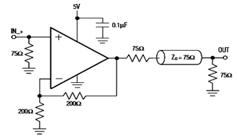
The diagram below illustrates a typical operating circuit for the video line driver using the IC4030/4031 schematic. It incorporates the MAX4030E/MAX4031E, which are unity-gain stable operational amplifiers that offer high-speed performance, rail-to-rail outputs, and 15kV ESD protection, as stated...

This circuit is sensitive to low-frequency electromagnetic radiation and can detect hidden wiring or the field surrounding a transformer. A radial type inductor is used as a probe, which effectively responds to low-frequency changing magnetic and electric fields. Ordinary...
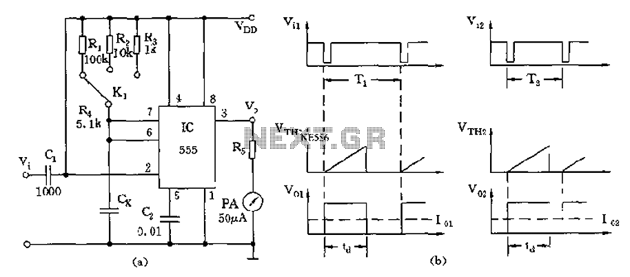
The circuit utilizes a 555 timer along with timing resistors R1 to R3 and a measured capacitance Cx to create a capacitance meter. The principle of capacitance measurement in a one-shot circuit is based on the relationship between the...
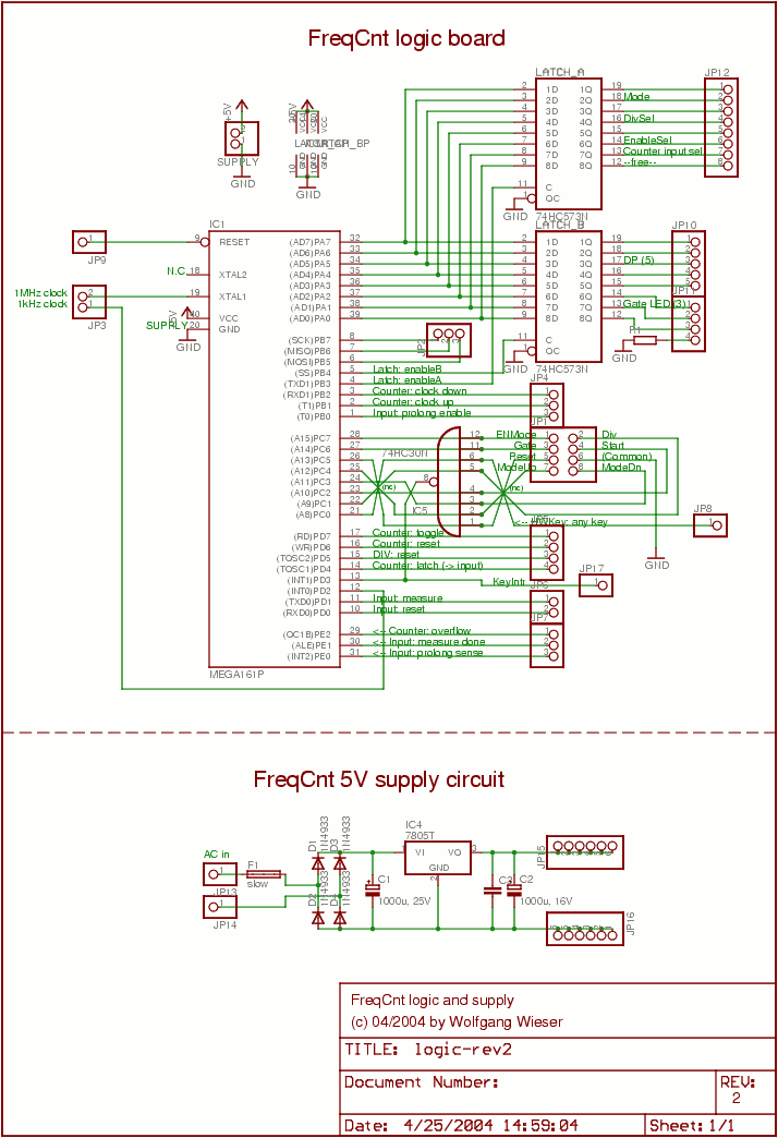
The lower schematic represents a standard bidirectional rectifier along with capacitors and a 7805 voltage regulator, which provides a stable 5V source to power the electronic components of the frequency counter. A fuse is included for security purposes. The...
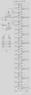
The diagram illustrates a circuit comprising 10 identical units, each varying only in the capacitance values of their capacitors, which determine the frequency band for each filter. Potentiometers are utilized to adjust the designated frequency regions in each unit....
Flyback LED drivers are versatile as they can be utilized in applications with input voltages either above or below the necessary output voltages. They feature a straightforward circuit configuration that maintains a constant LED current without the need for...