
Programmable Code Lock circuit
The described programmable code lock circuit operates on a voltage range of 6 to 15 volts, making it versatile for various applications. The use of CMOS technology ensures low power consumption, allowing for battery operation. The circuit employs two distinct types of thumbwheel switches: TWS1 to TWS8 function as decimal-to-BCD converters, while TWS9 to TWS16 serve as a 10-input multiplexer, providing flexibility in input selection.
Each combination of a decimal-to-BCD switch and a multiplexer switch is interfaced with the CD4028B BCD to decimal decoder, resulting in eight unique digital outputs. These outputs feed into the CD4068 8-input NAND gate, which requires matching inputs from the respective switch pairs to generate a logic high signal at specific outputs. The critical operation involves ensuring that the selected decimal numbers from TWS1 and TWS9 match, which is fundamental to achieving the desired output.
When the outputs from the thumbwheel switches match, the NAND gate transitions from a high to a low state, producing a clock pulse that triggers the CD4024B 7-stage counter configured as a flip-flop. The output Q0 from this flip-flop drives a relay driver circuit composed of transistors T1 and T2. The relay activates when Q0 transitions to a low state, allowing for control over the load connected through the relay contacts.
Switch S1 is integrated into the design to provide a manual mechanism for locking and unlocking the relay circuit. Once the correct code is inputted, the NAND gate remains in a low state, permitting the flip-flop to be toggled freely, thus enabling or disabling the relay as needed. This feature allows authorized personnel to control devices, such as a deck, by providing power through the relay contacts.
After usage, the authorized user can disable the system by operating switch S1 and altering the positions of TWS1 through TWS8, ensuring that no valid code is present. This action effectively locks the system, preventing unauthorized access. The concealment of switches TWS9 through TWS16 enhances security, as these switches are not accessible after the code is set. Additionally, DIP switches may be employed as an alternative to thumbwheel switches for user convenience and configuration flexibility.A programmable code lock can be used for numerous applications in which access to an article/gadget is to be restricted to a limited number of persons. Here is yet another circuit of a code lock employing mainly the CMOS ICs and thumbwheel switches (TWS) besides a few other components.
It is rugged and capable of operation on voltages ranging between 6 and 15 volts. The supply current drain of CMOS ICs being quite low, the circuit may be operated even on battery. The circuit uses two types of thumbwheel switches. switch numbers TWS1 through TWS8 are decimal-to-BCD converter type while switch numbers TWS9 through TWS16 are 10-input multiplexer type in which only one of the ten inputs may be connected to the output (pole). One thumbwheel switch of each of the two types is used in combination with IC CD4028B (BCD to decimal decoder) to provide one digital output.Eight such identical combinations of thumbwheel switches and IC CD4028 are used. The eight digital outputs obtained from these combinations are connected to the input of 8-input NAND gate CD4068.For getting a logic high output, say at pole-1, it is essential that decimal numbers selected by switch pair TWS1 and TWS9 are identical, as only then the logic high output available at the Specific output pin of IC1 will get transferred to pole-1.
Accordingly, when the thumbwheel pair of switches in each combination is individually matched, the outputs at pole-1 to pole-8 will be logic high.This will cause output of 8-input NAND gate IC CD4068b to change over from logic high to logic low, thereby providing a high-to-low going clock pulse at clock input pin of 7-stage counter CD4024B, which is used here as a flip-flop (only Q0 output is used here).The output (Q0) of the flip-flop is connected to a relay driver circuit consisting of transistors T1 and T2. The relay will operate when Q0 output of flip-flop goes low. As a result transistor T1 cuts off and T2 gets forward biased to operate the relay.Switch S1 is provided to enable switching off (locking) and switching on (unlocking) of the relay as desired, once the correct code has been set.
With the code set correctly, the NAND gate output will stay low and flip-flop can be toggled any number of times, making it possible to switch on or switch off the relay, as desired. Suppose we are using the system for switching-on of a deck for which the power supply is routed via the contacts of the relay.
The authorised person would select correct code which would cause the supply to become available to the deck. After use he will operate switch S1 and then shuffle the thumbwheel switches TWS1 through TWS8 such that none of the switches produces a correct code.
Once the code does not match, pressing of switch S1 has no effect on the output of the flip-flop.Switches TWS9 through TWS16 are concealed after setting the desired code. In place of thumbwheel switches TWS1 through TWS8 DIP switches can also be used. 🔗 External reference
Related Circuits
Various values of D3 can be utilized to achieve different output voltages ranging from approximately 0.6V to around 30V. It is important to note that at elevated voltages, the circuit's performance may diminish, potentially resulting in lower current output....
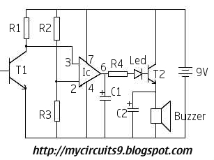
In this fire alarm circuit, a thermistor functions as the heat sensor. As the temperature rises, its resistance diminishes, and conversely, when the temperature falls, its resistance increases. At standard temperature, the resistance of the thermistor (TH1) is approximately...
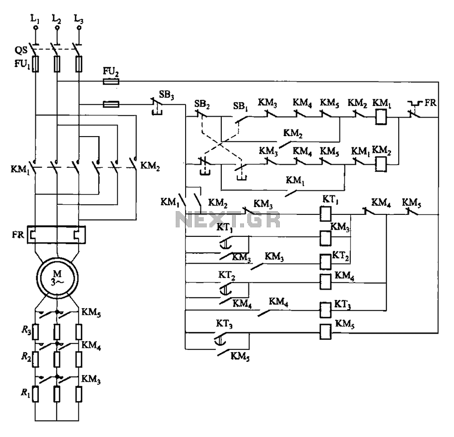
The circuit depicted in Figure 3-162 includes several components: SBi serves as the forward start button, SBz functions as the reverse start button, and SB3 is designated as the stop button. The resistance levels for the start switches are...
The circuit presented is an integrated circuit (IC) controlled emergency light. Its key features include automatic activation of the light during mains failure and a battery charger equipped with overcharge protection. In the absence of mains power, relay RL2...
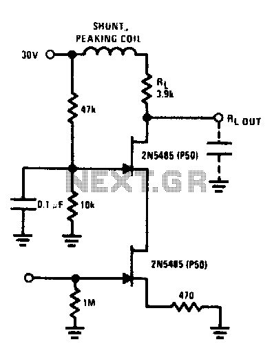
The FET cascode video amplifier exhibits very low input loading and minimizes feedback to nearly zero. The 2N5485 transistor is utilized due to its low capacitance and high transconductance (YfS). Additionally, the bandwidth of this amplifier is constrained by...
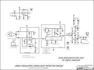
This circuit activates an alarm whenever an object crosses the laser beam emitted by a laser. The output of the IC TL071 goes high when the laser beam is interrupted. This output voltage is further amplified by an NPN...
Warning: include(partials/cookie-banner.php): Failed to open stream: Permission denied in /var/www/html/nextgr/view-circuit.php on line 713
Warning: include(): Failed opening 'partials/cookie-banner.php' for inclusion (include_path='.:/usr/share/php') in /var/www/html/nextgr/view-circuit.php on line 713