
Programming PIC 16F84A
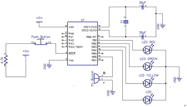
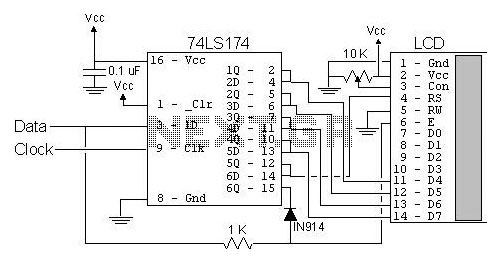
The analysis of the PIC microcontroller's configuration begins with a thorough examination of its datasheet, which serves as a critical resource for understanding the operational parameters and pin assignments. For instance, bit 3 of Port B (RB3) is essential for specific applications and is located at pin 9 in the DIP and SOIC packages. The significance of accurately interpreting the pin diagram, as illustrated in Table 1-1 of the datasheet, cannot be overstated. It provides a visual representation of the microcontroller's layout, which is vital for correct circuit design.
When reviewing the provided schematic, it is important to approach it with a critical mindset. The presence of errors may indicate either a misunderstanding of the schematic's intent or a pedagogical strategy employed by the instructor to promote independent learning. Identifying these errors is a valuable exercise, as it reinforces the importance of the datasheet as a primary reference document.
In debugging the associated code, the MPLAB Simulator serves as an invaluable tool. By stepping through the code, one can monitor the values assigned to each register, ensuring they align with the expected outcomes. This process not only facilitates the identification of logical errors but also enhances the understanding of the microcontroller's operation. Engaging with the datasheet and simulator in this manner fosters a deeper comprehension of electronic design and programming, ultimately leading to more robust and functional circuit implementations.After answering all those questions, to yourself, and geting the answers and/or decisions on that, some serious studying of the PIC datasheet is the next step ion order to know what the steps for each configuration and other details. Not quite. It is bit 3 of Port B, not pin 3 which is RA4. RB3 is on pin 9 of the PIC (for the DIP & SOIC packages). Look at the pin diagram (Table 1-1) in the data sheet. Still, the schematic you posted has many thing wrong. Are you sure this is exactly as your lecturer gave it to you Or maybe the errors are on purpose to see if you read the data sheet to get this circuit to work. Therefore we`ll point out the errors but not the solutions, that`s up to you to learn. As to whether the code might work, use the MPLAB Simulator to Step through your code. When you step through the code check that every register gets the value it should. This should always be to first step in debugging and will catch many `dumb` errors. 🔗 External reference
Related Circuits

Over the weekend, an attempt was made to perform mechanical work by machining acrylic material to create a joint using a stepper motor. The effort was unsuccessful, particularly when trying to score and snap the acrylic, as cutting lengths...

A typical liquid crystal display inverter circuit (OZ965) is primarily controlled by the OZ965 chip. It includes a driving field effect transistor (U2), a step-up transformer, the backlight socket, and associated circuitry. A 5V DC voltage is provided by...
This is a simple servo tester which will comprehensively test the capabilities of almost any modern servo. It has two pushbuttons, CENTRE and SWEEP and a potentiometer which works as follows: - CENTRE Does exactly that, centers the servo,...
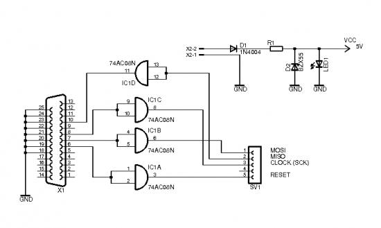
The brain of the robot is composed of an Atmel Tiny2313 microcontroller. This MCU features In-System Programming, allowing programming of its memory using a low-cost programmer. A simple programmer connects to the parallel port and is described in the...
This project is provided as a prototyping project as no PC board has been produced. The photographs show the project built on a matrix board using surface-mount components and very fine wire. The final design will require a double-sided...
The most popular LCD interface is the Hitachi 44780 based LCD controller chip which provides a fairly easy to work with interface and low power consumption. The major drawback of the interface is the perceived complexity of working with...