
Servo tester with PIC12F675
The described servo tester circuit utilizes a PIC12F675 microcontroller, which serves as the central processing unit for controlling the operation of the servo motor. The circuit is designed to test the functionality and performance of various servo motors through two primary modes: centering and sweeping.
In the centering mode, activated by the CENTRE pushbutton, the microcontroller sends a control signal to the servo, positioning it at its neutral or center point. The position can be fine-tuned by adjusting the attached potentiometer (R5 = 5K), allowing for precise control of the servo's angle. The potentiometer functions as a variable resistor, altering the voltage supplied to the servo, thus determining its position.
The sweeping mode, initiated by the SWEEP pushbutton, allows the servo to oscillate between its minimum and maximum positions. The rate of this oscillation is adjustable via the same potentiometer, providing the user with control over the sweep speed. The microcontroller employs its internal timer to generate a consistent pulse width modulation (PWM) signal with a frame duration of 20 ms, which is standard for most servo motors. The duty cycle of the PWM signal, which dictates the on/off ratio, can be modified by the user to achieve different behaviors in the servo's movement.
The passive components play crucial roles in the circuit's stability and functionality. Resistors R1 (1K), R2 (10K), R3 (82R), and R4 (10K) are used for biasing and signal conditioning, while capacitors C1 (27pF), C2 (27pF), and C3 (100nF) are employed for decoupling and filtering, ensuring stable operation of the microcontroller and reducing noise in the power supply lines. The zener diode (D1 = 4.7V) is utilized for voltage regulation, protecting the microcontroller from overvoltage conditions. The crystal oscillator (Q1 = 10MHz) provides the necessary clock signal for the microcontroller's operations, ensuring accurate timing for the PWM generation.
Overall, this servo tester circuit is a practical tool for evaluating servo performance, offering features that allow for both static positioning and dynamic sweeping, while ensuring robust operation through careful component selection and configuration.This is a simple servo tester which will comprehensively test the capabilities of almost any modern servo. It has two pushbuttons, CENTRE and SWEEP and a potentiometer which works as follows: - CENTRE Does exactly that, centers the servo, afterwards the potentiometer determines position.
- SWEEP Sweeps the servo back and forth at a rate determined by the potentiometer setting. The PIC uses its internal timer to set up a constant frame duration of 20ms and the on/off ratio is set by the user. Parts: R1 = 1K R2 = 10K R3 = 82R R4 = 10K R5 = 5K potentiometer C1 = 27pF C2 = 27pF C3 = 100nF D1 = 4,7V zener diode Q1 = 10MHz crytal IC1 = PIC12F675 🔗 External reference
Related Circuits

This is a simple servo tester designed to thoroughly evaluate the capabilities of nearly any modern servo. It features two pushbuttons, labeled CENTRE and SWEEP, along with a potentiometer that functions in the following manner: The servo tester circuit is...
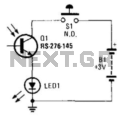
Using a battery, a phototransistor, and a visible-light LED, this simple circuit functions as a "go/no go" tester for infrared remote control devices. The illumination of the LED indicates that the phototransistor is being modulated by infrared energy. This circuit...

A servo is an error-sensing feedback control mechanism used to correct the performance of a system. A servo motor is a DC motor equipped with a servo mechanism. A servo motor is an electromechanical device that utilizes a closed-loop control...
The shaft can be positioned at specific angular positions by sending a coded signal to the servo. As long as the coded signal is present on the input line, the servo will maintain the angular position of the shaft....
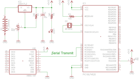
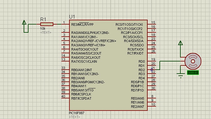
There are two schematics to examine for constructing a transmitter/receiver system. The first schematic is the transmitter, featuring a variable trimpot connected to RA0. The trimpot's value will be transmitted from the Tx pin of the PIC to the...
Servos are valuable components for various applications, including robotics, automation, and remote control tasks, such as steering model vehicles. They are relatively inexpensive and readily available; however, controlling them can be somewhat challenging as they require specific timing to...