
Proteus
The described software is a comprehensive tool designed for electronic engineers and PCB designers, facilitating both schematic capture and PCB layout processes. The automatic component placement feature enhances workflow efficiency by allowing the software to intelligently position components based on pre-defined design rules and constraints. Track routing capabilities enable the automatic connection of components, ensuring optimal signal integrity and layout efficiency.
The full-feature schematic capture environment supports a wide range of components and allows for the creation of complex circuits with ease. Users can design PCBs either automatically, utilizing the software's intelligent algorithms, or manually, providing flexibility based on project requirements or personal preferences.
Support for power planes is crucial in modern PCB design, as it allows for the efficient distribution of power across the board while minimizing electromagnetic interference. The software’s ability to output designs in industry-standard CADCAM formats ensures compatibility with various manufacturing processes, facilitating a smooth transition from design to production.
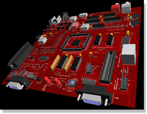
An integrated 3D viewer enhances the design experience by allowing users to visualize the PCB in three dimensions, aiding in the assessment of component placement and board size. This feature is particularly useful for identifying potential mechanical issues before fabrication.
The inclusion of an interactive SPICE circuit simulator allows for real-time testing and validation of circuit designs within the software environment. This capability enables users to simulate circuit behavior, analyze performance metrics, and troubleshoot issues preemptively, significantly reducing the likelihood of errors during the manufacturing phase. This comprehensive toolset makes the software an invaluable asset for electronic design projects.Professional schematic capture and PCB design software with automatic component placement, track routing and design validation. Includes full feature schematic capture environment. Create PCBs automatically or manually from a schematic. Extensive support for power planes. Outputs to industry standard CADCAM formats. Integrated 3D Viewer provides board visualisation during design. Interactive SPICE circuit simulator included with all 🔗 External reference
Related Circuits
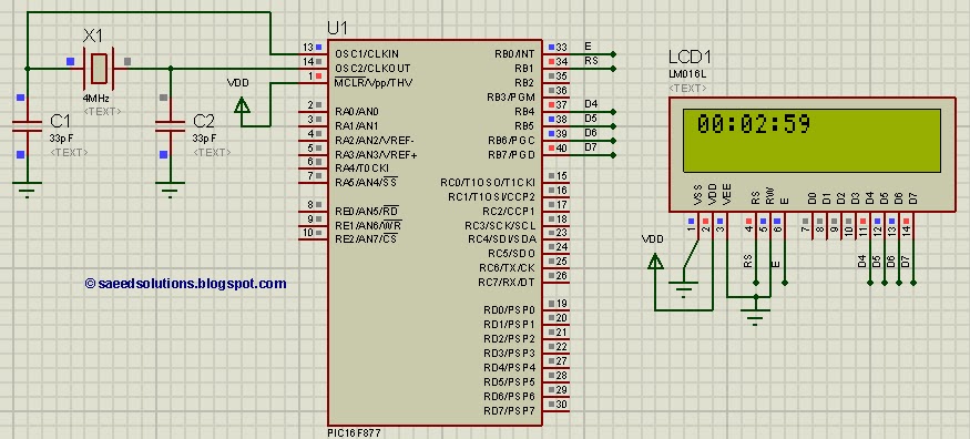
This tutorial on the PIC16F877 microcontroller addresses the question, "How to implement a digital clock using the PIC16F877?" The use of the PIC16 simulator (Proteus) is included. The PIC16F877 microcontroller is a versatile and widely used component in embedded systems,...
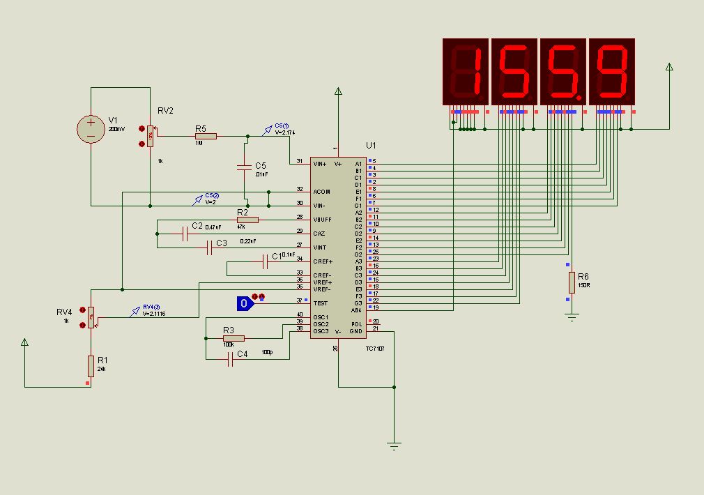
This document presents new models of a 3-digit common cathode (CC) and common anode (CA) multiplexed 3-digit voltmeter chip, specifically the TC7107 (ICL7107). It features a thumb switch with a common pin for BCD and hexadecimal outputs. The TC7107 is...

The first schematic page contains the primary content of the design, while the second page features simulation support circuitry. The primary design controls the accessory relays and indicators. It also drives the control loop and adjusts the throttle control...
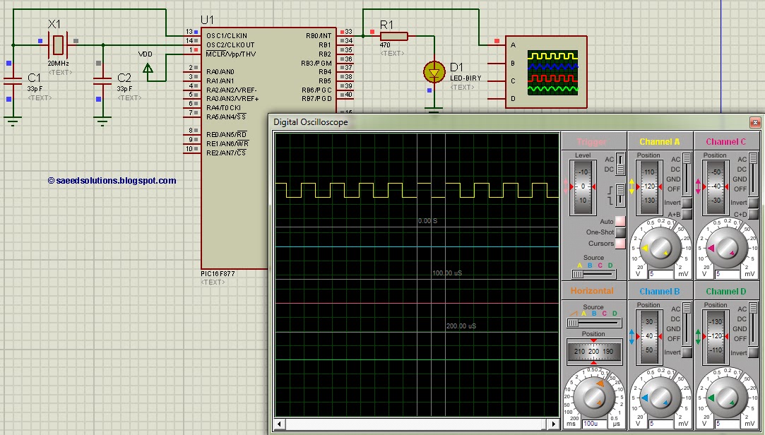
This tutorial on the PIC16F877 microcontroller addresses the question of how to utilize Timer0 and manage its interrupts. It utilizes the PIC16 simulator for demonstration purposes. The PIC16F877 microcontroller is a versatile device widely used in embedded systems. Timer0 is...
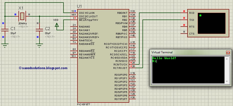
This post addresses the inquiry, "How to use interrupt-based UART in PIC16F877?" Additionally, the PIC16 simulator (Proteus) can be utilized to verify this UART code and its functionality. The PIC16F877 microcontroller features a Universal Asynchronous Receiver-Transmitter (UART) that can be...
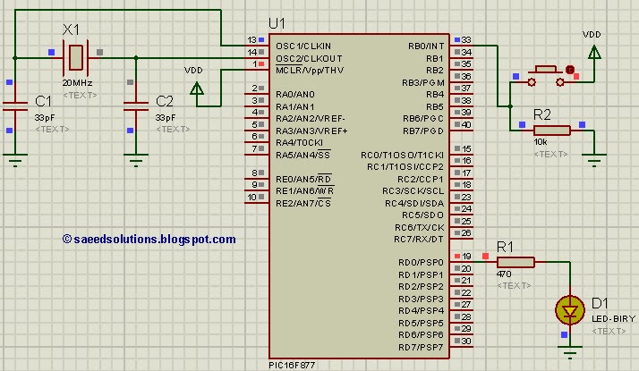
This post addresses the question, "How to capture a pulse to generate an interrupt in PIC16F877?" Additionally, the PIC16 simulator (Proteus) can be utilized for verification. To capture a pulse and generate an interrupt in the PIC16F877 microcontroller, the configuration...