
Proximity Alarm

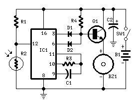
The circuit described utilizes three inverters (U1a, U1b, and U1c) configured in a manner that forms an RC oscillator. The oscillation frequency is contingent upon the resistance (R1) and capacitance values (C1 and C2) selected, as well as the inherent characteristics of the inverter IC. The oscillation generates a square wave output, which is then processed by a voltage coupling stage consisting of capacitors C3, C4, and diode D2. This stage rectifies the oscillating signal, producing a positive DC voltage.
The output of the voltage coupling circuit feeds into the input of the third inverter (U1c). In its low state, U1c ensures that transistor Q1 remains off, preventing the activation of the piezo buzzer (BZ1) and thereby silencing any sound output. The sensitivity of the circuit can be adjusted by tuning the values of capacitors C1 and C2. When these capacitors are set to their most sensitive point, the circuit can detect a hand placed within a range of 3 to 5 inches, triggering an alert when this threshold is crossed.
To initiate the circuit, it is recommended to set C1 and C2 to approximately half of their maximum capacitance values and then apply power. Upon powering the circuit, it should begin oscillating, allowing for the detection mechanism to function as intended. This design exemplifies a straightforward yet effective approach to creating a proximity sensor with audible alert capabilities.Inverters U1a and U1b are connected in a simple RC oscillator circuit. The frequency is determined by the values of R1, C1 C2 and the internal characteristics of the integrated circuit. As long as the circuit is oscillating, a positive dc voltage is developed at the output of the voltage-couple circuit: C3, D2 and C4.
The dc voltage is applied to the input of U1c-the third inverter amplifier-keeping its output in a low state, which keeps Q1 turned off so that no sound is produced by BZ1. With C1 and C2 adjusted to the most sensitive point, the pickup plate will detect a hand 3 to 5-inches away and sound an alert. Set C1 and C2 to approximately one-half of their maximum value and apply power to the circuit. The circuit should oscillate and 🔗 External reference
Related Circuits

This is a door knob touch alarm designed for home security purposes. The alarm is activated when someone touches the metal door knob. However, this circuit will not function on a fully metal door. The door knob touch alarm circuit...
This circuit activates an alarm whenever an object crosses the laser beam emitted by a laser. The output of the IC TL071 goes high when the laser beam is interrupted. This output voltage is further amplified by an NPN...

A CMOS 4060 burglar alarm circuit. This is a single-zone alarm with automatic exit, entry, and siren cut-off timers. It will accommodate all the usual types of normally-closed input devices, such as magnetic reed contacts. The CMOS 4060-based burglar alarm...
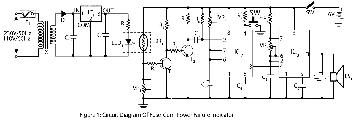
The Fuse Cum Power Failure Indicator utilizes a thermistor and a timer IC (NE555) in its circuit design. The circuit diagram includes a parts list for the fuse cum power failure indicator, which signals instances of power failure. The Fuse...
This circuit, enclosed into a small box, is placed in the fridge near the lamp (if any) or the opening. With the door closed the interior of the fridge is in the dark, the photo resistor R2 presents a...
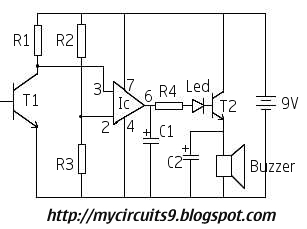
This is an alarm circuit that activates when motion is detected. Upon detection, the circuit triggers an alarm buzzer, which remains activated until the power is disconnected. This type of alarm circuit is commonly used to monitor areas for...
Warning: include(partials/cookie-banner.php): Failed to open stream: Permission denied in /var/www/html/nextgr/view-circuit.php on line 713
Warning: include(): Failed opening 'partials/cookie-banner.php' for inclusion (include_path='.:/usr/share/php') in /var/www/html/nextgr/view-circuit.php on line 713