
Door Knob Touch Alarm

The door knob touch alarm circuit utilizes a capacitive sensing technique to detect the presence of a person's hand near the door knob. The core components of the circuit typically include a capacitive sensor, a microcontroller or comparator for signal processing, and an audible alarm or notification system.
When a person approaches the door and touches the metal knob, the capacitive sensor detects the change in capacitance caused by the human body. This change triggers the microcontroller, which processes the signal and activates the alarm system. The alarm can be configured to emit a sound through a buzzer or send a notification to a connected security system.
It is important to note that the effectiveness of this circuit is limited to non-metallic doors or doors with non-conductive surfaces, as the presence of a fully metal door would interfere with the capacitive sensing mechanism. To enhance the performance of the circuit, it may be beneficial to incorporate additional features such as adjustable sensitivity settings or a delay mechanism to prevent false alarms due to incidental contact.
The schematic for this circuit typically includes a power supply section, the capacitive sensor input, the signal processing unit, and the output stage connected to the alarm system. Proper layout and grounding techniques should be employed to minimize interference and ensure reliable operation.This is door knob touch alarm for your home security purpose. The alarm will be activated when someone touch the metal door knod. This circuit wont work on full metal door. Download the schematic drawing This is door knob touch alarm for your home security purpose. The alarm will be activated when someone touch the metal door knod. This ci rcuit won`t work on full metal door. 🔗 External reference
Related Circuits

This alarm circuit was designed to monitor a mains-powered smoke detector located in a shed used for housing dog kennels. It provides complete isolation. This alarm circuit is engineered to ensure the safety of a shed environment, specifically designed for...

This alarm circuit is designed to monitor a mains-powered smoke detector located in a shed used for dog kennels. It ensures complete isolation from the mains, allowing low-voltage (12V) cabling to run to the alarm circuit, which is situated...

This is a straightforward 12V rechargeable smart battery charger circuit. It can be utilized as a charger for car batteries, inverter batteries, emergency light batteries, and more. An automatic indicator alarm circuit accompanies this battery charger schematic. The primary...
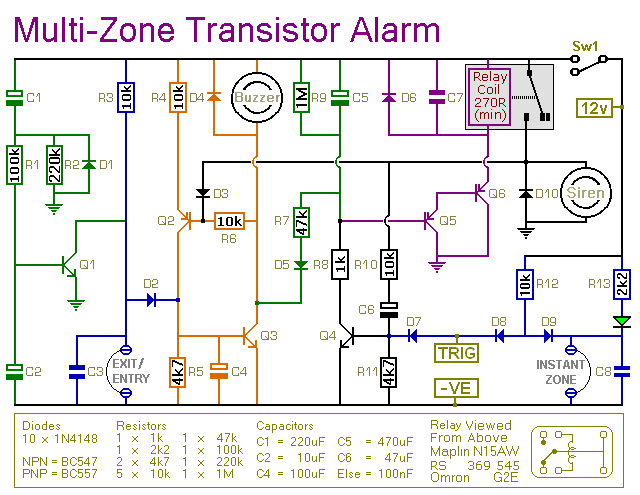
This transistor-based alarm system incorporates automatic exit and entry delays, along with a timed bell cut-off and system reset functionality. In addition to the exit/entry zone, the fundamental alarm board includes one instant zone, which is sufficient for many...
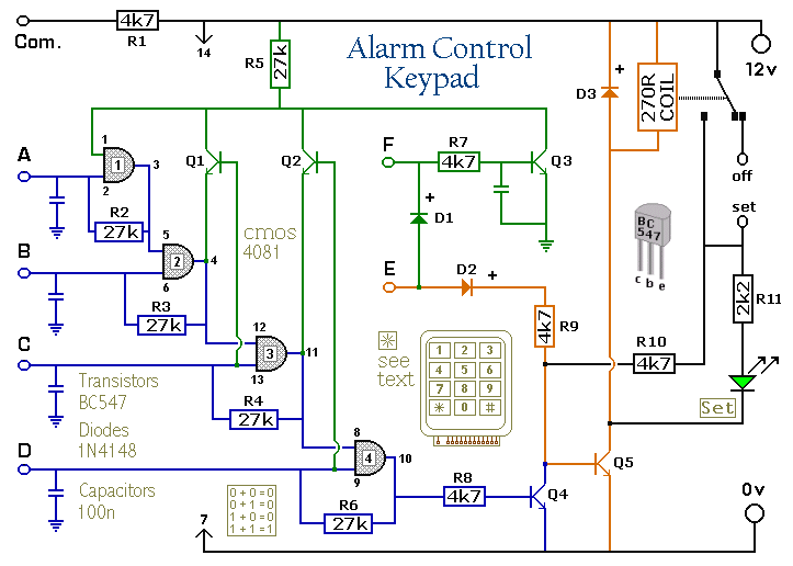
The Keypad must be the kind with a common terminal and a separate connection for each key. On a 12-key pad, look for 13 terminals. The matrix type with 7 terminals will NOT do. The Alarm is set by...

The circuit generates a warble-tone alarm signal that simulates the sound of a British police siren. IC1 is configured as an alarm generator, while IC2 operates as a 1 Hz astable multivibrator. The output from IC2 is utilized to...