
Pseudorandom-Sequential Ring-Modulated Tone Generator

The circuit design employs a 16-bit serial shift register, which is essential for generating a series of pseudorandom tones. The clocking mechanism provided by the multivibrator ensures that the data is shifted through the register at a consistent rate, allowing for rapid tone generation. The use of exclusive-NOR gates for data feedback is crucial, as it facilitates the creation of complex waveforms by mixing the outputs of the two oscillators. The interaction between the two oscillators, controlled by different bits from the shift register, allows for a rich variety of tones that can be produced.
The audio oscillators utilize inverters and an analog switch to create square wave outputs, which are then mixed to generate a more complex audio signal. The careful selection of resistors to offset the frequencies of the oscillators is instrumental in achieving a broad spectrum of tones. The ability to adjust the duration of the output sequence provides flexibility for live performances, allowing the musician to tailor the effect to suit the context of the music.
The power management aspect of the circuit is designed to be efficient, utilizing CMOS technology to minimize power consumption. This is particularly advantageous for battery-operated devices, as it extends operational time significantly. The inclusion of a Schottky rectifier not only protects the circuit but also ensures reliability during use.
Overall, this circuit exemplifies a sophisticated approach to sound generation, combining digital and analog techniques to produce unique audio effects suitable for a variety of applications, particularly in musical compositions and performances.The circuit illustrated produces a short duration of rapidly-sequencing tones, invoking the stereotypical sonic imagery of a sophisticated computer, such as would be scripted for the science-fiction genre. I designed this circuit for use in the composition "Be Quite Still, " by the popular band, "The Cassettes.
" A similar riff had been provided by a Moog Rogue analog synthesizer for the band`s studio recording, but dedicating the synthesizer to just this brief effect, alone, would have prevented its use for other parts of the composition in live peformances. The circuit is comprised of a 16-bit serial shift register (U3 and U4), clocked by multivibrator U1A-U1F, and employing data feedback via three exclusive-nor gates, U2B, C, and D.
This implements a digital word generator that propagates pseudorandom data through the register, of which the first four bits are used to control the frequency of an audio oscillator, comprised of inverters U1B-U1C and quad analog switch U5. Similarly, bits 5 through 8 control a second audio oscillator, comprised of U1D-U1E and U6. The two squarewave oscillator outputs are fed to exclusive-nor gate U2A, which combines them in a manner similar to a ring-connected diode mixer, producing sum and difference frequencies of the two squarewaves, resulting in harmonically-complex tones at the AUDIO OUT jack.
Flip-flops U7A and U7B, voltage regulator U8, and associated components form a power-control circuit that provides voltage to the tone generator for a duration of about two seconds. The duration is adjustable by varying the 270K resistor. U7B ensures that the circuit turns off after the last tone is completed, thus preventing the annoyance of a short interval at the end of the effect.
To provide a large variety of tone pairs, the two squarewave oscillators are offset in frequency by using an 82K resistor in one, and a 100K resistor in the other. A momentary closure of the RUN switch will initiate atwo-second sequence. If the switch is held closed for a longer period, the sequence will continue while the switch is held, and end as soon as the switch is released.
Given the considerable length of the generated code, and the 256 possible squarewave pairs, the circuit will produce an extremely long sequence before repeating. The use of CMOS devices in the power control section eliminates the need for an on-off switch, since standby current is essentially zero.
The circuit consumes less than 3 milliamperes while operating, providing extensive battery life. The 1N5817 Schottky rectifier prevents damage to the CMOS devices in the event of accidental battery reversal. In constructing this circuit, it is recommended that the U1 inverter sections "A" through "F" are allocated exactly as shown, since rearranging the otherwise-identical sections may cause sufficient coupling between the two audio oscillators for phase-locking, evident as "dead" tone intervals.
Click here for an audio sample of this circuit`s output. 🔗 External reference
Related Circuits

Six preset controls and seven selector switches enable a vast range of different sounds to be produced and altered at will. Such sounds as steam trains chuffing, helicopters flying, bird chirping, and machine guns firing are possible, as well...
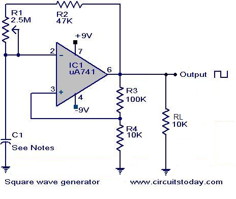
Square wave generator using uA741. Circuit diagram, theory, and working principle. The square wave generator utilizing the uA741 operational amplifier (op-amp) is a fundamental circuit widely employed in various applications, including signal processing, waveform generation, and timing applications. The uA741...

Fast rise and fall times necessitate the utilization of high-speed switching transistors for the differential pair, Q4 and Q5. Linear ramps and sine waves can be produced using the suitable reference input. The circuit employs high-speed switching transistors, specifically Q4...
Three circuit options Can be synchronized to Christmas tree flashing lights This circuit generates a dual-tone bells ringing similar to most door-bell units. It can be used in many applications other than door-bell. In the Notes below several options...
This circuit allows for the superimposition of a title and/or the time and date on an incoming video signal, which is particularly useful when editing video tapes. With the advent of affordable CCD camera modules, setting up a personal...
This type of design can produce a very high amperage current for a fraction of a second that can be used to do some useful work if properly harnessed. The switching device could be a rotating spark gap as...