
Bells ring Generator

The circuit described is a versatile dual-tone generator that can be utilized in various applications, including doorbells and decorative lighting systems such as synchronized Christmas tree lights. The primary function of this circuit is to produce two distinct tones: a "Ding" sound when the push button P1 is pressed and a "Dong" sound when the button is released.
The circuit employs integrated circuits (ICs) to generate these tones. Specifically, IC1D functions as the first-tone frequency generator, producing the "Ding" sound. This IC is typically configured as an astable multivibrator, which oscillates at a frequency determined by external resistors and capacitors connected to its pins. When P1 is pressed, the output of IC1D activates, generating the initial tone.
Upon releasing P1, IC1F takes over as the second-tone frequency generator, producing the "Dong" sound. Similar to IC1D, IC1F is also configured as an astable multivibrator, but its frequency is set differently to create a distinct sound that complements the first tone.
Transistors Q2 and Q5, along with associated passive components, serve as amplifiers and switches within the circuit. They help drive the output load, ensuring that the generated tones are sufficiently loud for the intended application. The arrangement of these components allows for flexibility in the circuit, enabling it to be adapted for various sound output requirements.
The circuit can be further enhanced by incorporating additional features such as volume control, tone modulation, or synchronization capabilities for visual indicators like flashing lights. This makes it suitable for a range of festive or signaling applications, providing an engaging auditory experience.Three circuit options Can be synchronized to Christmas tree flashing lights This circuit generates a dual-tone bells ringing similar to most door-bell units. It can be used in many applications other than door-bell. In the Notes below several options will be given in order to suit different needs. The circuit as shown in the diagram generates a "Ding-tone" when P1 is pressed and a "Dong-tone" when P1 is released. IC1D is the first-tone frequency generator and IC1F generates the second-tone. Q2, Q5 and related components act as 🔗 External reference
Related Circuits
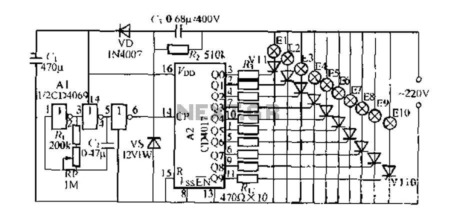
The digital integrated circuit consists of a controller for a string of ten road flashing lights, which drives the El-El0 string lights in a flashing cycle. The system utilizes a ten-count decoder, specifically the CD4017 digital integrated circuit. When...

A tapped-coil Colpitts oscillator is utilized at Q1 to deliver four tuning ranges: 1.7 to 3.131 MHz, 3.0 to 5.6 MHz, 5.0 to 12 MHz, and 11.5 to 31 MHz. A Zener diode (D2) is incorporated at Q1 to...
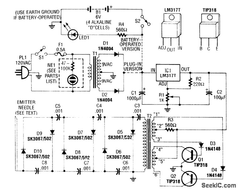
A modified black and white television flyback transformer is utilized in this circuit alongside a voltage multiplier to generate a negative voltage ranging from 9 kV to 14 kV. This high voltage is connected to a discharge needle to...
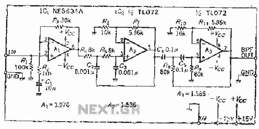
The filter incorporates a zoom function, with a front satin amplifier magnification calculated as d = 10/2.515 = 3.97, which results in a total beam compared to a 10 times magnification. The low-pass filter parameters are specified as a...
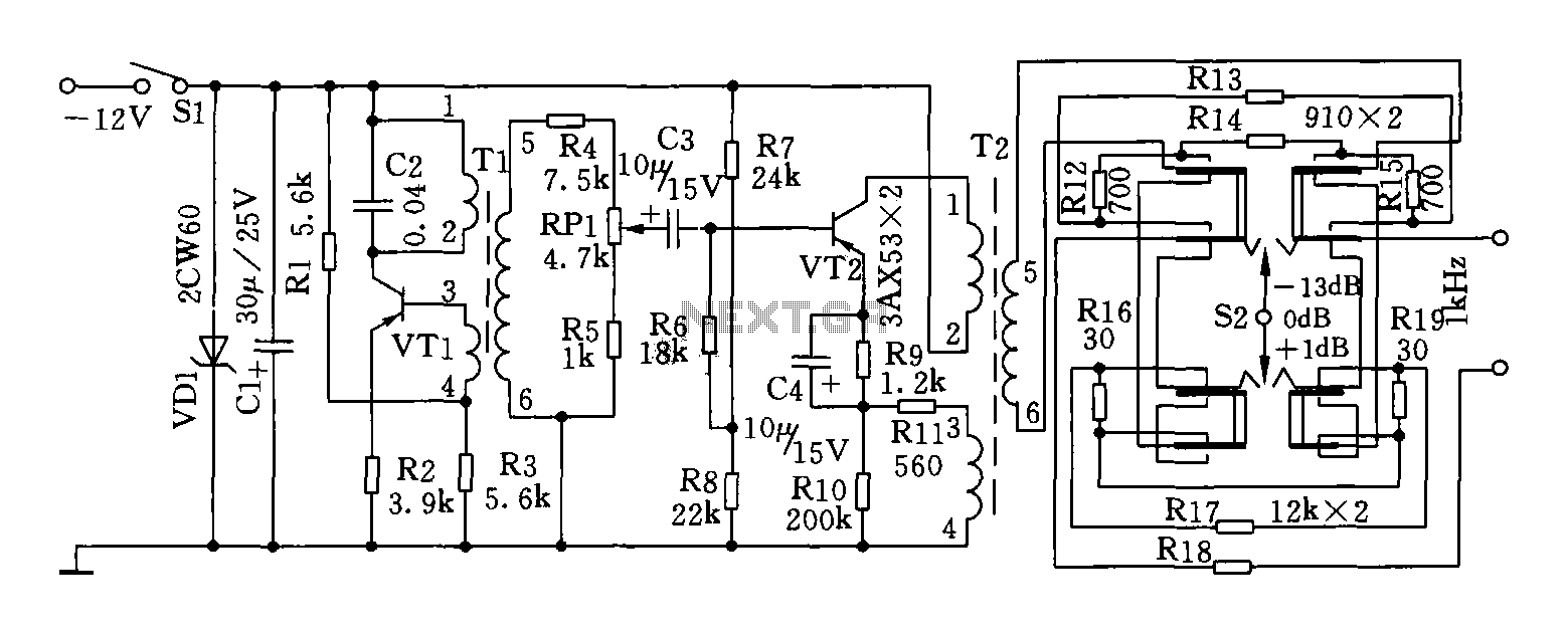
This circuit can generate a signal of 1 kHz and offers three output level options. It is suitable for testing communication equipment maintenance and barriers, providing a quick and accurate method to identify points of failure in televisions, stereos,...
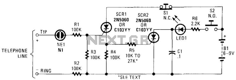
In this circuit, the ringing voltage on a telephone line causes NE-1 to break over, triggering SCR1, which in turn triggers SCR2. If a call has been received, depressing S2 will cause LED1 to light. Depressing S1 resets the...