
puff to off circuit
The circuit operates primarily through a combination of a condenser microphone, transistors, and an LED. The condenser microphone (M1) serves as a sensor that converts sound waves, specifically the breath of a user, into an electrical signal. This signal is typically a low-level voltage that needs amplification to be effective in controlling other components of the circuit.
Transistor Q1 functions as an amplifier. When the microphone detects a breath, it generates a voltage signal, which is fed into the base of Q1. As the sound pressure increases, the output voltage from the microphone rises, causing Q1 to conduct more current. This results in a higher voltage at the collector, which is then coupled to the emitter of the transistor pair Q2 and Q3.
Transistors Q2 and Q3 are configured in a push-pull arrangement. When the S1 button is pressed, it provides the necessary biasing to turn on Q2 and Q3. This allows current to flow from the power supply through the LED, illuminating it. The LED remains on as long as Q2 and Q3 are activated.
However, once the breath signal dissipates and the voltage from the microphone falls below a certain threshold, Q1 stops conducting, which in turn deactivates Q2 and Q3. This results in the LED turning off. To reactivate the LED, the user must press the S1 button again, resetting the circuit.
The design of this circuit emphasizes a simple yet effective method of controlling an LED based on sound pressure, showcasing the use of basic electronic components such as microphones, transistors, and LEDs in a straightforward application. The schematic would typically illustrate the connections between these components, including the power supply, the microphone, the various transistors, and the LED, ensuring clarity in how the circuit operates as a whole.This is a circuit diagram of a simple circuit in which the LED burning can be activated only by a gust OFF. A condenser mic (M1) is used to feel your breath. When the S1 button is pressed, transistors Q2 and Q3 as a couple wires attached will be activated and drives LED shines.
LED remains in this condition. When you puff on a condenser mic, the s ound pressure converted into a voltage signal at the output. This voltage signal is amplified by the transistor Q1. Since collector of Q1 coupled to the emitter of the pair attached, the couple will stop doing as there ever was a signal from a condenser mic for panting and the LED will go OFF. Push button switch S1 should be pressed again to turn the LED ON. The following is a schematic drawing: 🔗 External reference
Related Circuits
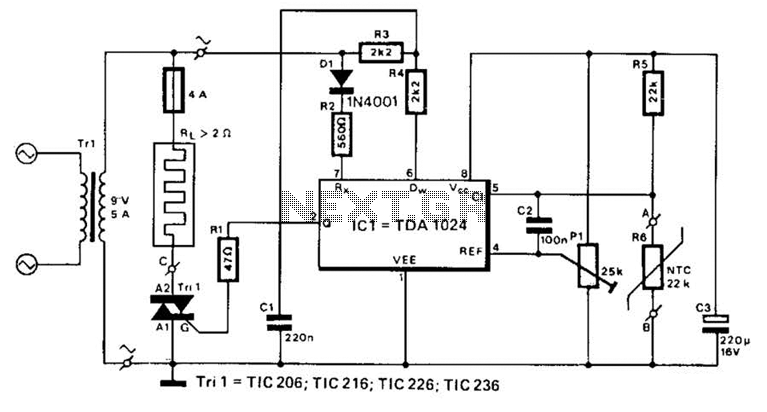
A TDA1024 electronic thermostat measures soil temperature using thermistor R6. The circuit employs zero-crossing switching to control the heater, which is constructed from elastic-coated steel wire. A potentiometer (PI) is utilized to adjust the temperature setting. The heater must...
Voltage regulator ICs from the 78xx series deliver a stable output voltage in contrast to a highly variable input supply, provided that the common terminal is grounded. Any voltage applied above zero volts (ground) to the common terminal is...
This is a birthday heart circuit. No much description is available but you can use your experienced imagination! The birthday heart circuit is designed to create a visually appealing display, often used as a decorative element for celebrations. The circuit...
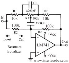
This topic discusses a resonant equalizer, which is a distinct type of circuit compared to the standard audio equalizer, although both achieve similar outcomes. The key difference is that the frequency responses of both the high and low frequency...
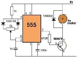
This project utilizes a 555 timer to control the speed of a 6-volt DC motor. Speed adjustment is achieved by rotating a 50 kΩ potentiometer either to the left or right. The circuit employs the 555 timer in astable mode,...
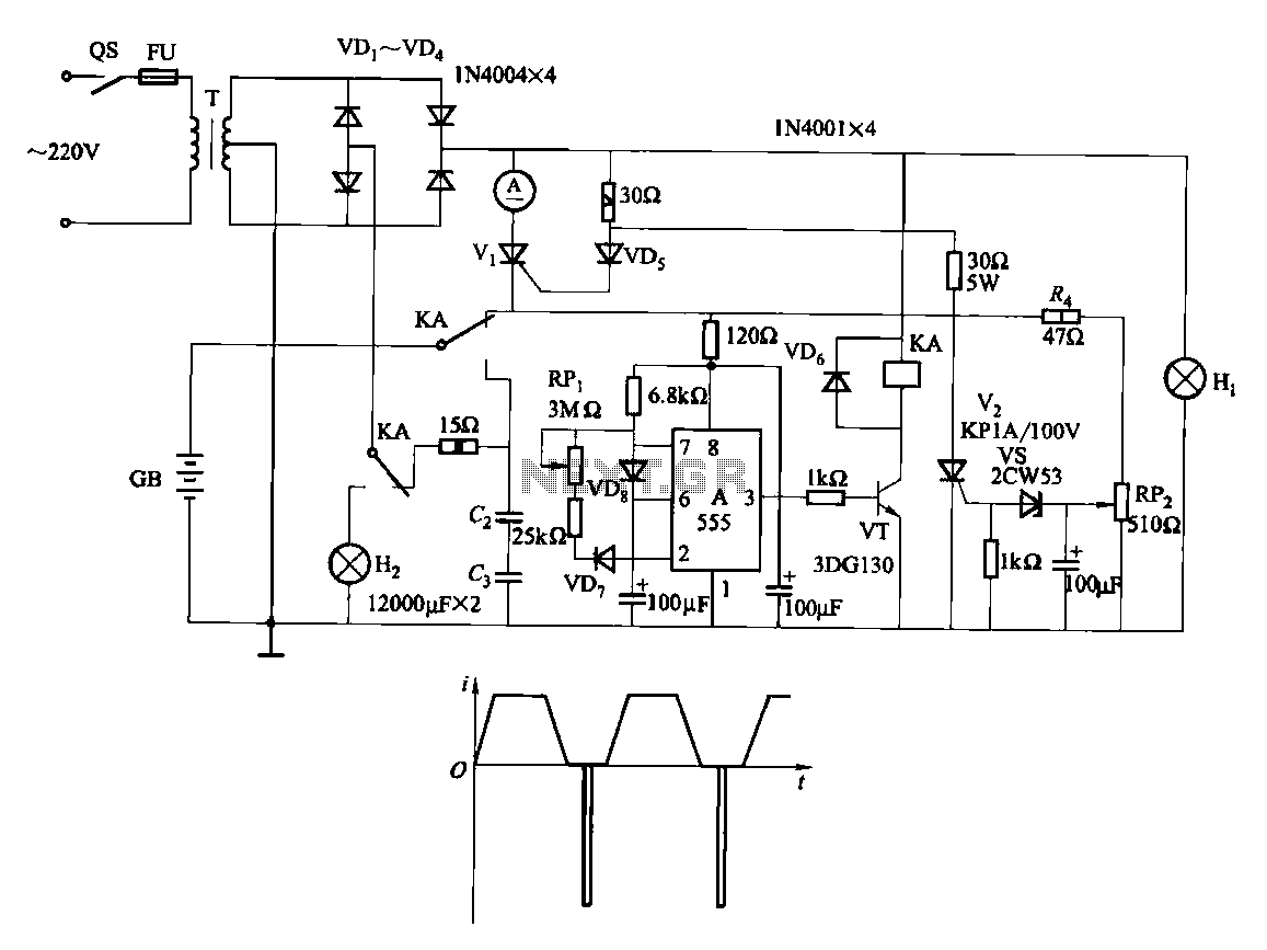
Fast and efficient charging is significantly higher than conventional charging, achieving a current charge that is ten to several times greater. When the battery voltage reaches a predetermined level (known as the polarization point), polarization within the cell becomes...