
Pulse Generator Produces 3-Phase Output

The three-phase pulse generator circuit is designed to create three-phase output signals that are phase-shifted by 120 degrees, resembling the characteristics of a standard three-phase AC power supply. The circuit typically consists of several key components, including oscillators, flip-flops, and output drivers, which work together to generate the desired waveforms.
At the core of the circuit, a stable clock signal is generated using an oscillator, such as a 555 timer or a microcontroller. This clock signal serves as the timing reference for the entire circuit. The oscillator output is fed into a series of logic gates or flip-flops, which are configured to produce the three-phase signals. Each output from these components is delayed appropriately to achieve the necessary phase shifts.
The output stage of the circuit often includes power transistors or MOSFETs that amplify the pulse signals to the required voltage and current levels for driving loads. The use of these components ensures that the circuit can effectively manage the power requirements of connected devices, such as motors or transformers, which typically operate on three-phase AC power.
To enhance the performance and stability of the circuit, filtering components may be incorporated at the output stage. These may include inductors and capacitors that help to smooth out the pulse signals, reducing harmonics and providing a cleaner output waveform. Additionally, protective components such as diodes may be included to safeguard against voltage spikes and ensure the longevity of the circuit.
This three-phase pulse generator circuit finds applications in various fields, including industrial automation, motor control systems, and renewable energy systems, where three-phase power is essential for efficient operation.This is a schematic diagram of a three-phase pulse generator circuit. This circuit produce 3 phase overlapped output similar with 3 phase AC powerline, you.. 🔗 External reference
Related Circuits
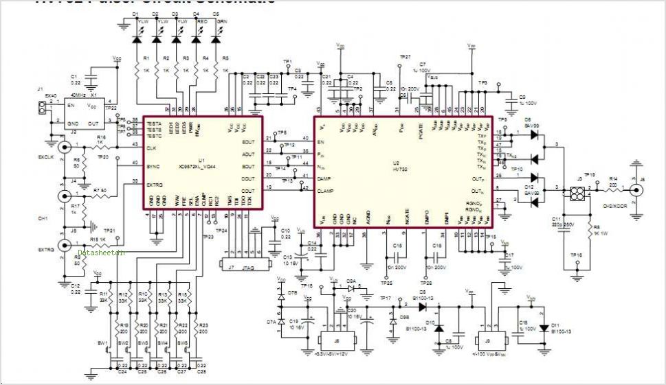
The Supertex HV7370 is a four-channel, high-speed, high-voltage ultrasound transmitter damper, while the HV748 is a four-channel, high-speed, high-voltage ultrasound transmitter pulser. Both integrated circuits (ICs) are intended for medical ultrasound imaging applications and can also be utilized as...
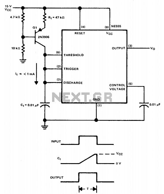
The linear charging ramp is particularly beneficial in applications requiring linear voltage control. Potential uses include long-duration voltage-controlled timers, voltage-to-pulse width converters, and linear pulse width modulators. Q1 acts as the current source transistor, providing a constant current to...
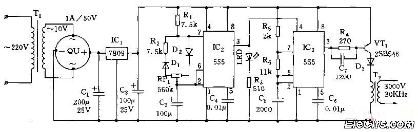
Adjust the RP1 to modify the pulse duty cycle of IC2, which in turn alters the pulse oscillation time of IC3. This regulation allows for the control of ozone generation time, effectively changing the concentration of ozone in the...
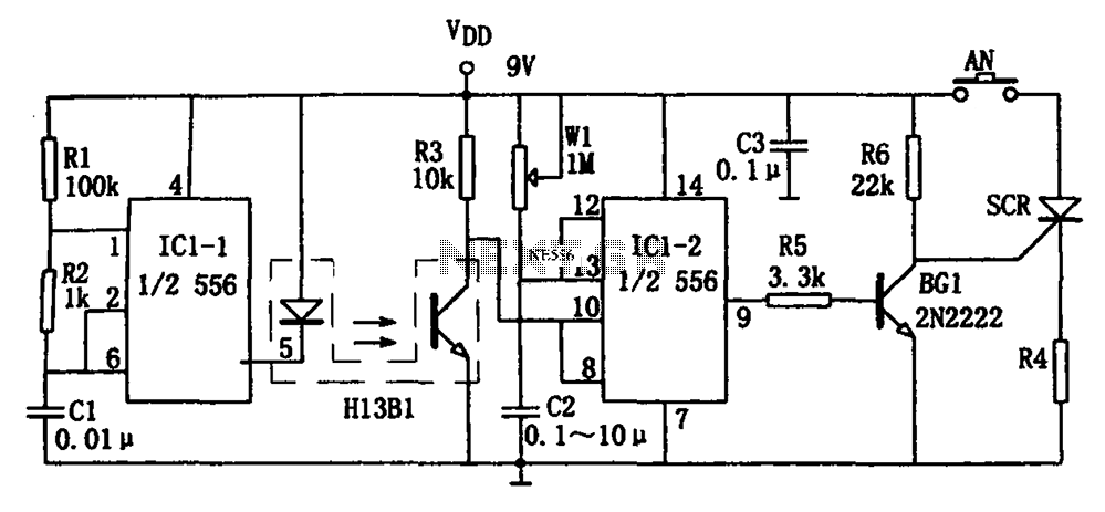
The circuit shown is a photoelectron pulse missing detection circuit. It includes an optoelectronic slotted switch H13B1, a dual time base circuit using a 556 timer IC, and several RC components that form a one-shot multivibrator. The design incorporates...
This circuit generates a two-tone effect similar to the cuckoo song. It can be used for doorbells or other applications due to a built-in audio amplifier and loudspeaker. As a sound effect generator, it can be connected to external...
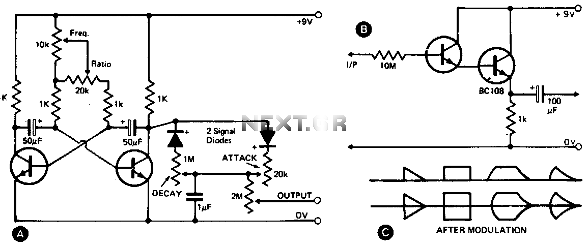
This waveshape generator functions as a slow-running oscillator with adjustable attack and decay times. It features a variable amplitude output, which is high impedance and can be controlled through a 2M potentiometer. Additionally, an add-on circuit is illustrated in...