
Pulse Width Modulator Using 555 IC
A pulse width modulator (PWM) is an essential component in various electronic applications, particularly in motor control, power regulation, and signal processing. The PWM signal is characterized by its ability to maintain a fixed frequency while adjusting the duration of the high state (duty cycle) based on an input modulating signal. This modulation allows for efficient control of power delivery to devices, enabling precise control over performance characteristics such as speed and torque in motors or brightness in LED lighting.
In a typical PWM circuit, the core components include a comparator, a reference voltage source, and a timing circuit. The comparator compares the modulating signal, which can be a sinusoidal waveform or any other varying signal, against a triangular or sawtooth waveform generated by the timing circuit. When the modulating signal exceeds the reference waveform, the output of the comparator switches high, creating a pulse. The width of this pulse is determined by the amplitude of the modulating signal at the moment of comparison, effectively varying the duty cycle.
The frequency of the PWM signal is determined by the timing circuit, which sets the rate at which the triangular or sawtooth waveform oscillates. The choice of frequency is critical and should be tailored to the specific application, balancing factors such as response time and efficiency. For instance, in motor control applications, a lower frequency might be preferable to reduce audible noise, while higher frequencies may be used in applications requiring rapid response times.
Additionally, filtering components may be included in the circuit to smooth out the PWM signal, converting it into a more stable DC voltage if needed. This is particularly useful in applications where a steady voltage is required, such as in power supplies or when driving analog devices.
Overall, the design of a PWM circuit involves careful consideration of component selection, waveform characteristics, and operational requirements to achieve the desired control and efficiency in electronic systems.Pulse width modulator produce a PWM signal, a pulse with a constant frequency but with the duty cycle vary according to a modulating signal. Here is the. 🔗 External reference
Related Circuits
This device was originally designed to test the Shutter Time Meter, which is specifically intended for analog SLR cameras. To accurately measure a camera's exposure time, it must first be checked with a well-defined signal. This circuit serves that...
The first positive pulse from a classic 555-based oscillator is always 1.6 times longer than the subsequent pulses. This discrepancy arises because, during the initial cycle, capacitor C2 begins charging from 0 V. While this is typically not an...
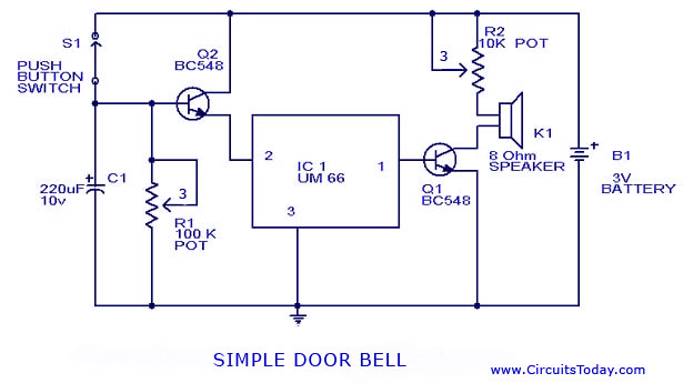
A simple doorbell circuit diagram and schematic designed using the UM66 IC, which is a music sound generator. This is an easy-to-make electronic doorbell circuit. The doorbell circuit utilizes the UM66 integrated circuit, known for its capability to generate musical...
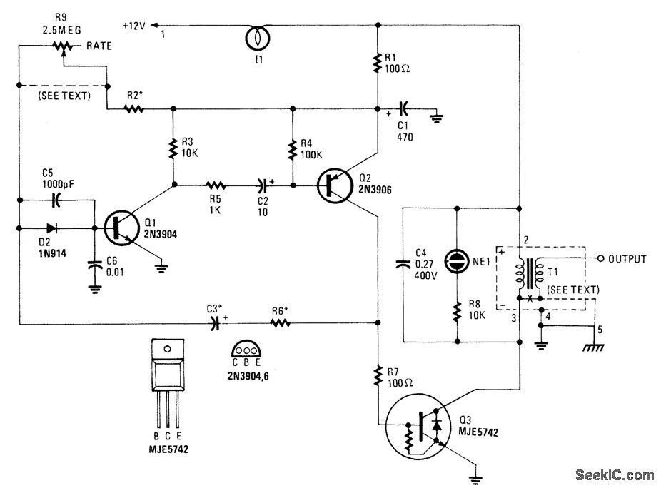
This high-voltage pulse supply generates pulses up to 30 kV. Transistors Q1 and Q2 create a multivibrator in conjunction with peripheral components R1 through R6 and capacitors C1, C2, C3, C5, C6, and diode D2. Resistor R9 adjusts the...
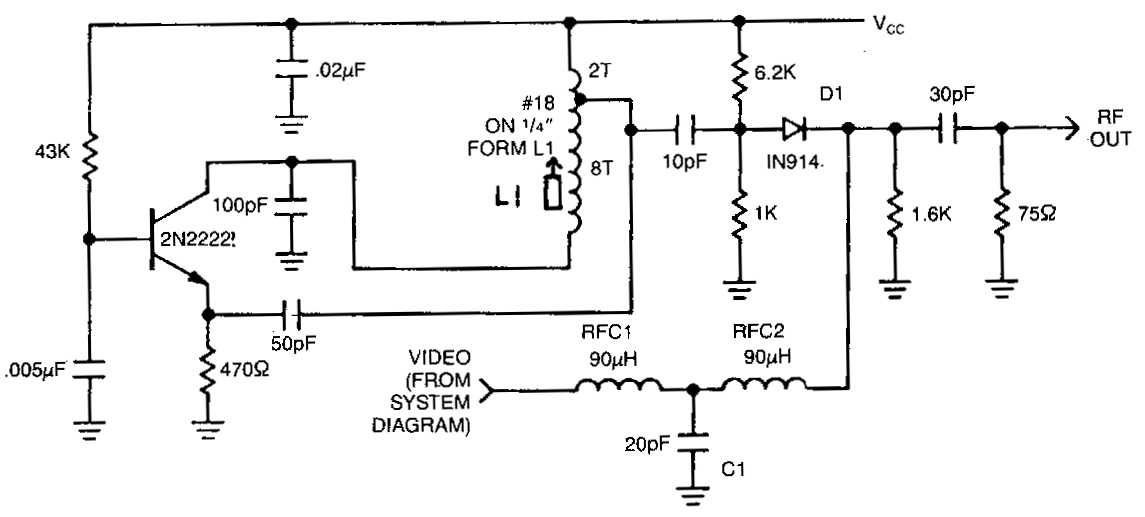
This circuit utilizes an oscillator (2N2222) and a diode (D1) as a nonlinear mixer. The frequency is determined by a slug in L1. RFCl, C1, and RFC2 create a low-pass filter designed to pass video signals while blocking RF...
Some time ago, a 1-key keyboard project was developed. The ATTiny microcontroller has been a recurring consideration since then. The 1-key keyboard project utilizes the ATTiny microcontroller, a compact and efficient device suitable for a variety of embedded systems applications....
Warning: include(partials/cookie-banner.php): Failed to open stream: Permission denied in /var/www/html/nextgr/view-circuit.php on line 713
Warning: include(): Failed opening 'partials/cookie-banner.php' for inclusion (include_path='.:/usr/share/php') in /var/www/html/nextgr/view-circuit.php on line 713