
Pulse Width Modulation DC Motor Controls

The described PWM control circuit offers an efficient method for regulating DC motor speed by utilizing a switching mechanism that modulates the power delivered to the motor. The circuit consists of a PWM generator, typically implemented with a 555 timer IC or a microcontroller, which produces a square wave signal. This signal is fed into a power transistor (Q1), which acts as a switch to control the current flowing to the motor (M1).
The duty cycle of the PWM signal—defined as the ratio of the ON time to the total time period—determines the average voltage and current supplied to the motor. By adjusting the duty cycle, the effective power delivered to the motor can be finely tuned, allowing for precise speed control.
In this configuration, the motor should be rated for a maximum operating voltage of 6V, and care must be taken to ensure that the current drawn by the motor does not exceed the maximum current rating of the transistor Q1. If a higher voltage is desired for the motor operation, it is permissible to connect a higher voltage source to the switch. However, it is critical to ensure that the power dissipation in Q1 remains within safe limits to prevent damage to the transistor.
The PWM control circuit is particularly beneficial in applications where variable speed control is necessary, such as in robotics, fans, or other automated systems. It provides a simple yet effective solution for controlling the speed of DC motors while maintaining efficiency and minimizing heat generation compared to linear control methods. Proper selection of components, including the transistor and motor, along with careful design of the PWM signal, will lead to optimal performance of the motor control system.This simple pulse width modulation DC motor control eliminates these problems. It controls the motor speed by driving the motor with short pulses. Thesepulses vary in duration to change the speed of the motor. The longer the pulses, the faster the motor turns, and vice versa. 2. M1 can be any DC motor that operates from 6V and does not draw more than the maximum current of Q1. The voltage can be increased by connecting the higher voltage to the switch instead of the 6V that powers the oscillator. Be sure not to exceed the power rating of Q1 if you do this. 🔗 External reference
Related Circuits
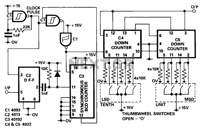
In applications where the period of the input pulses is uneven and a divider is required to accommodate a wide range of frequencies, a non-integer programmable pulse divider can be utilized. The D-type flip-flop (IC2) serves to synchronize the...
The objective is to operate a motor using an L293D Motor Drive Shield, which can handle 600mA per coil. The motor consumes 400mA per coil, suggesting compatibility. However, the datasheet does not clearly indicate the pinouts, only labeling them...
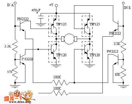
Regarding the DC motor control problem, this circuit is intended to assist individuals with specific requirements. The circuit's functions for co-rotation, rollback, deceleration, and stopping can be managed by the connected microcontroller unit (MCU). The DC motor control circuit is...
This circuit utilizes a dual-timer NE556 to generate 1Hz pulses spaced 5 seconds apart, with the option for manual or automatic operation. The NE556 integrated circuit (IC) consists of two independent timers. The NE556 timer is a versatile device that...
The 4027 is a dual JK flip-flop that features independent clock, set, and reset inputs for each flip-flop, making it suitable for toggle, register, and control functions. It is capable of driving two low-power TTL loads and employs a...
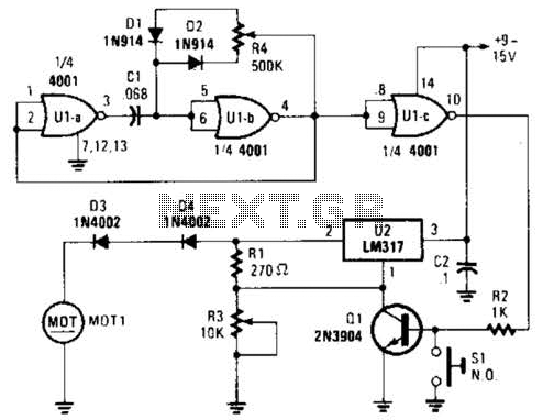
Connected in this manner, an LM317 1-A adjustable-voltage regulator can be utilized to control the speed of a miniature DC motor or to adjust the brightness of a small lamp. The circuit achieves this by modulating the pulse width,...