
Meter Adaptor With Symmetrical Input

An oscilloscope is a vital instrument in electronics for visualizing voltage signals over time. It provides a graphical representation of electrical signals, allowing engineers and technicians to observe waveforms, measure signal parameters, and diagnose issues in circuits. The input configuration of an oscilloscope is distinct from that of a standard voltmeter.
In an oscilloscope, the ground terminal (GND) is usually linked to the earth ground through the mains supply. This connection ensures that the oscilloscope operates safely and minimizes interference from external noise. The grounded input helps stabilize the measurements by providing a reference point for the signal being analyzed.
When connecting the oscilloscope to a circuit, it is essential to consider the input impedance, which is typically high (around 1 MΩ) for most oscilloscopes. This high impedance ensures that the oscilloscope does not significantly load the circuit under test, allowing for accurate measurements without altering the circuit's behavior.
The oscilloscope can display various signal characteristics, such as amplitude, frequency, and phase. It can capture both periodic and non-periodic signals, making it versatile for troubleshooting and analyzing different types of electronic circuits. Users can adjust the time base and voltage scale to zoom in on specific waveform details, enhancing the analysis capability.
Overall, the oscilloscope is an indispensable tool in modern electronics, providing insights into the dynamic behavior of electrical signals that cannot be achieved with simpler instruments like voltmeters.In contrast to an ordinary voltmeter, the input of an oscilloscope generally has one side (GND) connected to ground via the mains lead. In certain situati.. 🔗 External reference
Related Circuits
This circuit functions as a simple optical level indicator for sound signals, adaptable to various user needs. It allows for adjustments to input levels via trimmer potentiometers TR1 (Level) and TR2 (Gain). The signal is then rectified by diodes...

I made this project as a test to improve a technique to read analog values without analog-to-digital converter (ADC). I ended with this "sound meter". It may not work perfectly, it needs some improvement but works anyway. It has...
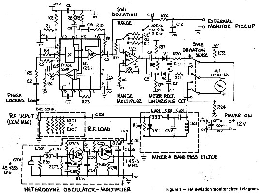
A deviation monitor can be constructed by connecting a frequency modulation (FM) detector to an AC voltmeter, calibrating the meter in units of frequency deviation. One method for detecting or demodulating the FM signal is via a phase-locked loop...
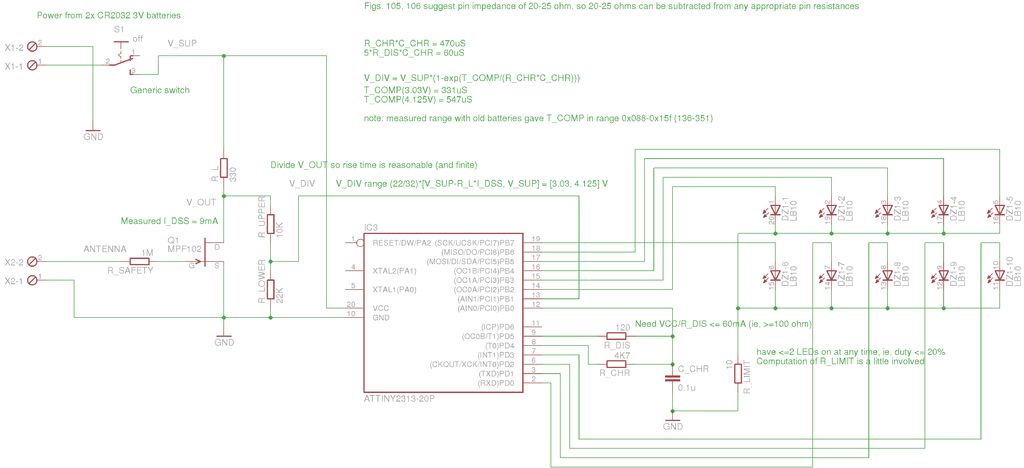
A method for measuring static electricity for a science project was sought. An old copy of "Getting Started in Electronics" by Forrest M. Mims III was referenced for guidance. To create a static electricity measurement circuit, a simple design can...
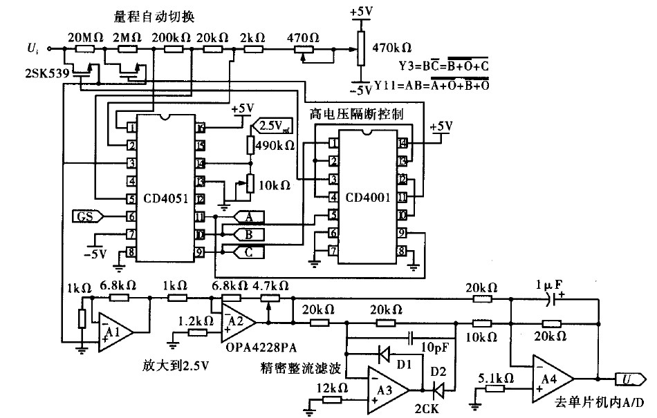
Voltage measurement is a fundamental aspect of electronic technology today, with increasing demands for accuracy and functionality in instruments. This is particularly critical when measuring signals with significant phase differences, as it is essential to ensure the accuracy of...

A control program typically requires more than simply turning outputs on and off; these actions are triggered by events. Such events are connected to the input of a microcontroller, which determines the subsequent actions. Inputs can originate from various...