
Tiny Tuned Loop Antennas
The antenna's operation in transmit mode is analogous to its operation in the receive mode. In receive mode, the quality of the receiving antenna directly influences the amplitude of the signal across it, which is affected by multiple factors. Understanding the relationship between these factors can aid in optimizing the design for specific applications. The formula that relates these factors indicates that as the carrier frequency increases, the number of turns on the antenna increases, the antenna's Q factor rises, the diameter of the antenna increases, and the strength of the RF magnetic field received by the antenna also increases. This leads to a larger output signal, which corresponds to greater sensitivity in the antenna's performance.
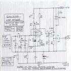
In terms of circuit design, a typical resonant loop antenna circuit consists of an inductor (the coil) and a capacitor connected in parallel. The inductor's inductance (L) and the capacitor's capacitance (C) determine the resonant frequency (f) of the circuit, which can be calculated using the formula:
\[ f = \frac{1}{2\pi\sqrt{LC}} \]
Where:
- \( f \) is the resonant frequency in Hertz (Hz),
- \( L \) is the inductance in Henries (H),
- \( C \) is the capacitance in Farads (F).
The choice of wire gauge for the coil and the number of turns will impact the quality factor (Q) of the antenna, which is a measure of its efficiency. A higher Q indicates a narrower bandwidth and better selectivity, which is desirable for receiving specific frequencies. The physical layout of the antenna, including its diameter and height above ground, will also influence its radiation pattern and impedance, which should be matched to the receiver for optimal performance.
In summary, the design of a resonant loop antenna involves careful consideration of coil dimensions, inductance, capacitance, and the relationship between these parameters to ensure effective operation in both transmit and receive modes.Loop Antennas are considered to be "samall" when their diameter drops below about 1/10 of the wavelength they are intended to be used at. In this case, I use the term "Tiny" because the antenna's diameter is about 1/30,000 the wavelength, and at 5.5 cm in diameter, they are quite small in human terms.
Coils are one of the few components experimenters can easily do a good job of making for themselves, and the coil, with or without the core, is the major component in a resonant loop antenna. The resonant loop antenna is fundamentally a parallel resonant LC circuit tuned to the carrier frequency.
A coil, or in some cases coils, of wire form the antenna, which is usually mostly inductive, and a parallel capacitance is used to make the antenna resonant at the desired frequency. Time varying magnetic fields from the signal source that cross the coils of wire induce current in the loop, which results in a voltage across the output.
The closer the incoming signal is to the loop's resonant frequency, the higher the output voltage. There are several formulae available for calculating the number of turns to use in a coil once you decide how much space you have for it, but I haven't found one that seems to get close enough to use without trimming. To get a loop of the desired inductance, I wind a coil of about the number of turns I expect to need, and then measure it.
Since inductance is proportional to the square of the number of turns in a coil, I calculate an inductance factor for that size coil, and then I use that inductance factor to calculate the number of turns I will need. If I am careful, this goes pretty quickly with only a couple of iterations before the inductance is close enough to work with.
The antenna's operation in transmit mode is analogous to its operation in the receive mode, so let's take the receive mode first. The better the receiving antenna, the larger the signal appearing across it, and a lot of factors affect the amplitude.
Looking at how these factors relate to one another (See Formula 1) can be useful in understanding how to optimize the design for a particular application. At first glance the formula may look a little intimidating, but all it really means is that the higher the carrier frequency, the more turns on the antenna, the higher the antenna's Q, the larger the antenna's diameter, and the stronger the RF magnetic field received by the antenna, the larger the signal at its output - larger signals on the output correspond to greater sensitivity.
🔗 External reference
Related Circuits
This circuit is designed to be used in conjunction with the standard 4 foot square loop used in MW for long distance reception. The described circuit is intended for use with a standard 4-foot square loop antenna, optimized for medium...
This 1 square meter antenna has radiation resistance of about 10 nanohoms, making the 0.4 Ohm resistance (including skin effect, which about doubled the resistance from the DC value) the dominant loss in the antenna. The lower the resistance,...
Sometimes, it is necessary for a program to halt execution while a specific condition remains true. This can be accomplished using a while loop. The following example illustrates the application of a while loop to calibrate the value of...
A simple, low component count phase locked loop that locks onto and detects the amplitude of an incoming baseband 7 bit Barker code using a switched resistor demodulator that is driven directly by a microcontroller's output pins. Balanced modulators...
A frequency reference for tuning up the RS-232 to 100 MHz RF desktop channel adapter elsewhere on this site, when I found this Saronix crystal oscillator in my junk box. A few minutes with AVRStudio produced an ATtiny12 to...
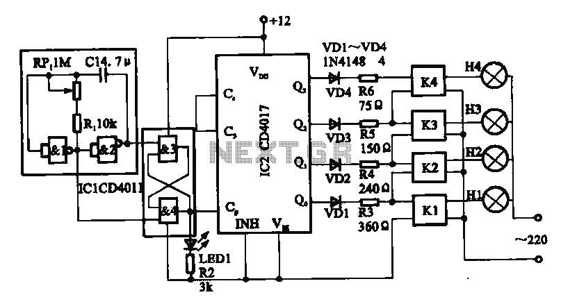
This circuit illustrates a circular lighting control system. It consists of four two-input NAND gates from the CD4011 series, which form a non-inverting multivibrator. This multivibrator generates a pulse that is used to shape the output of an RS...
Warning: include(partials/cookie-banner.php): Failed to open stream: Permission denied in /var/www/html/nextgr/view-circuit.php on line 713
Warning: include(): Failed opening 'partials/cookie-banner.php' for inclusion (include_path='.:/usr/share/php') in /var/www/html/nextgr/view-circuit.php on line 713