
Quartz 1Hz Timebase
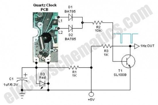
The 1Hz timebase generator circuit operates by leveraging the inherent frequency stability of the quartz crystal oscillator found in standard quartz clocks. The primary component is the quartz crystal, which oscillates at a specific frequency determined by its physical properties. In most quartz clocks, this frequency is typically 32.768 kHz.
To create a 1Hz output, a frequency divider circuit is required. This can be achieved using a series of flip-flops or a binary counter. A common approach is to use a 14-stage binary counter, such as the CD4040, which divides the input frequency by 2 for each stage. By connecting the output of the 14th stage, the 1Hz signal can be obtained from the original 32.768 kHz frequency.
The circuit configuration includes connecting the quartz crystal to the oscillator circuit, which is often built around an inverter or a dedicated oscillator IC. The output from this oscillator feeds into the input of the binary counter. Proper bypass capacitors should be used to stabilize the power supply to the oscillator and counter circuits, ensuring reliable operation.
Additionally, to visualize the output signal, an LED can be connected to the output pin of the final stage of the counter. This LED will blink at a 1Hz rate, providing a clear indication of the timebase signal.
For power supply considerations, a regulated DC voltage source, typically 5V, is suitable for powering the circuit. It is essential to ensure that the connections are secure and that the circuit is properly grounded to avoid any noise that could affect the accuracy of the timebase generation.
Overall, this simple circuit design combines the reliability of quartz timing with basic digital logic to produce a stable 1Hz output, suitable for various timing applications in electronics.Here is one basic circuit of a simple but accurate 1Hz timebase generator built around a standard Quartz clock circuit board. Just lift the clock PCB from any cheap quartz clock and carefully remove all extra components like the drive coil, buzzer, alarm switch and clock mechanism (quartz movement), etc.Next wire the circuit as shown in the schematic diagram..
🔗 External reference
Related Circuits
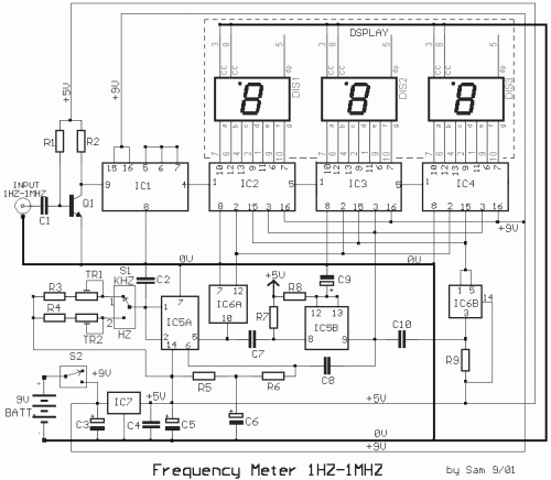
The circuit was designed to create a low-cost frequency meter that will cover the range of 1 Hz to 1 MHz with a digital indication using three 7-segment displays. The frequency meter circuit operates by measuring the frequency of an...
Electronics tutorial about quartz crystal oscillators, including harmonic, overtone, Pierce oscillator, and crystal quartz oscillator circuits. Quartz crystal oscillators are vital components in modern electronics, providing stable frequency references for a variety of applications. They utilize the piezoelectric properties of...
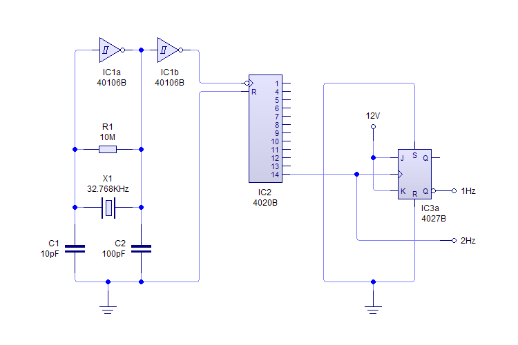
This plugin utilizes a quartz oscillator featuring a crystal (X1) to produce a 32,768 Hz (32,768 = 2^15) output. This frequency is fed into a 4020 14-Stage Ripple Counter, which divides the signal by 2^14, resulting in a 2...
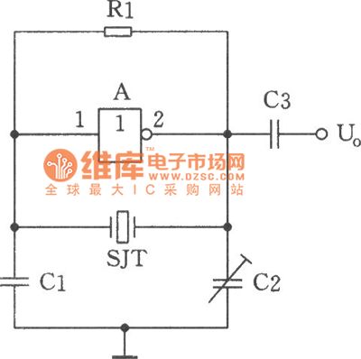
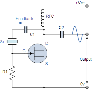
The image depicts a sine wave oscillator that consists of a quartz crystal (SJT) and gate A of the hex inverter IC CD4069. Compared to a standard RC phase-shift oscillator, the frequency stability of a crystal oscillator can achieve...
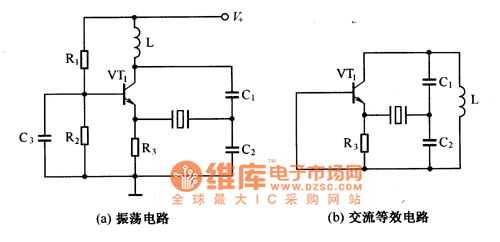
The oscillator that consists of a quartz crystal can be classified into two types: the parallel resonant type crystal oscillator and the series resonant type crystal oscillator. The parallel resonant type crystal oscillator and its AC equivalent circuit are...
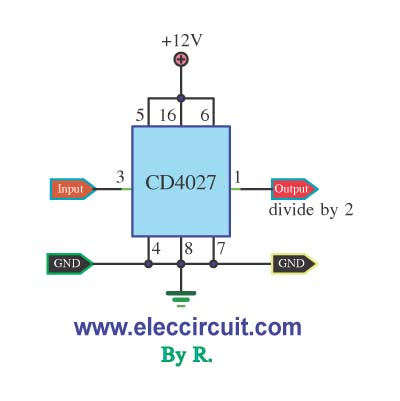
This circuit functions as a frequency divider, converting an input frequency of 10 Hz to an output frequency of 1 Hz. It is designed as a 10-divider circuit, which is particularly useful for applications such as standard digital clocks...