
Quick Counter For Young Children
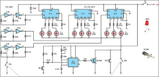
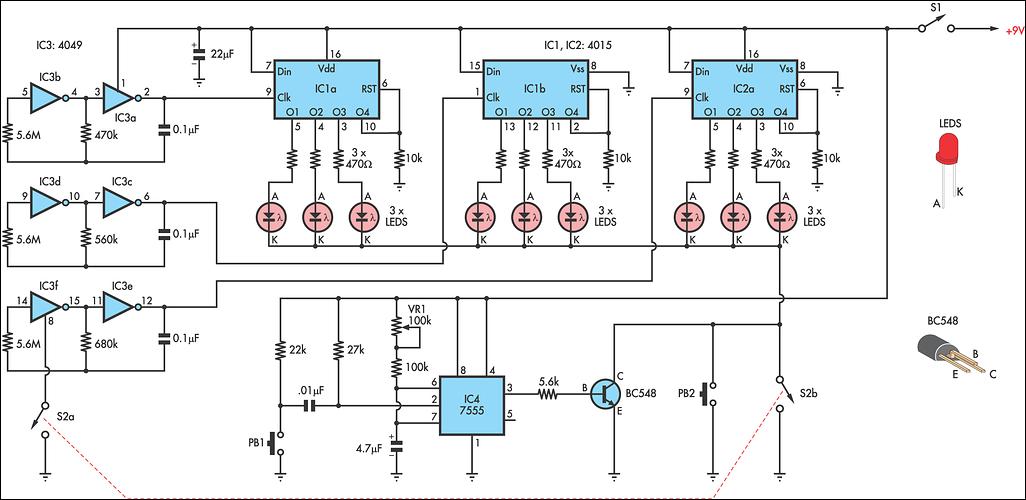
The circuit design incorporates several key components to facilitate its functionality. The 4049 hex inverter (IC3) serves as a versatile oscillator, generating clock pulses at different frequencies. These pulses are crucial for driving the 4015 dual 4-stage shift registers (IC1 and IC2), which sequentially activate the outputs that control the LEDs. The randomization of the LED illumination is achieved through the timing mechanism provided by the 7555 timer, allowing for a brief but effective display of the LEDs that children can count.
The configuration of the LEDs in a 3 x 3 grid not only provides a visually appealing layout but also enhances the learning experience by presenting numbers in various formats. This design encourages children to engage with the circuit actively, fostering both counting skills and cognitive recognition of patterns. The adjustable viewing time via VR1 allows for customization based on the child's pace, making the learning process adaptable and effective.
Overall, this circuit serves as an educational tool that combines electronic principles with interactive learning, providing an engaging way for children to practice counting while exploring basic electronics concepts. The thoughtful arrangement of components and the interactive features of the circuit work together to create a stimulating learning environment.This circuit is a toy to encourage young children to count. Power is turned on by switch S1, then S2 is closed. This makes nine LEDs flash slowly. S2 is then opened and the LEDs go out. Pressing pushbutton PB1 turns on a random number of LEDs - briefly - during which time they are to be counted. The number counted can be checked by pressing PB2 wh ich turns the same LEDs on for as long as needed. Then repeat. The circuit works as follows: IC3 is a 4049 hex inverter connected as three oscillators running at different rates. It is turned on by closing switch S2a. The clock pulses from IC3 drive both halves of IC1 and one half of IC2, both being 4015 dual 4-stage shift registers.
Each shift register has four outputs which go high in order: 1, 1 and 2; 1 and 2 and 3; 1 and 2 and 3 and 4. However as output 4 is connected to the reset line of its own half - the shift register resets to zero.
Outputs 1, 2 & 3 of all three shift registers are connected to nine LEDs, the cathodes of which go to a common rail. This rail is connected to ground via S2b when switch S2 is closed. When S2 is opened the three oscillators stop but a random number of LEDs is still connected to the high outputs of the 4015s.
That number can be viewed briefly by pressing PB1 which pulses the 7555 timer in monostable mode, to give a short duration output which drives Q1 and connects the LED cathodes to 0V. The viewing time is adjustable by VR1. Checking a count is done by pressing PB2 which holds the same LEDs on as long as desired. The LEDs are set in a 3 x 3 grid with the connection scattered, ie, the first row is not the three LEDs from the first half of IC1.
Note that, unlike the usual dice, a number such as 5 can appear in many formats, so pattern recognition is no help. Also note that this is not a nine output true dice - because the numbers do not come up with equal frequency.
🔗 External reference
Related Circuits
The lab project involves a BCD counter and a 7-segment display using the CD4510BMS presettable BCD Up/Down Counter. The objective is to count from 32 to 84, rather than the default range of 00 to 99. The current setup...
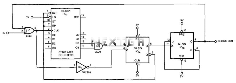
This circuit symmetrically divides an input by virtually any odd number. The circuit contains n + 1 clocks to achieve the desired divisor. By selecting the proper n, which is the decoded output of the 74LS161 counter, divisors from...
This simple counter can be utilized to count pulses and serves as the foundation for a customer counter, similar to those found at store entrances, or for any application requiring counting functionality. The circuit is compatible with any TTL...
This circuit is a toy designed to help young children learn to count. Power is activated by switch S1, followed by closing switch S2, which causes nine LEDs to flash slowly. When S2 is opened, the LEDs turn off....
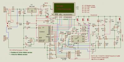
The following circuit illustrates a 40 MHz/400 MHz Frequency Counter Circuit Diagram. This circuit is based on the PIC16F84 IC. Features: The frequency counter circuit operates within the range of 40 MHz to 400 MHz, utilizing the PIC16F84 microcontroller...
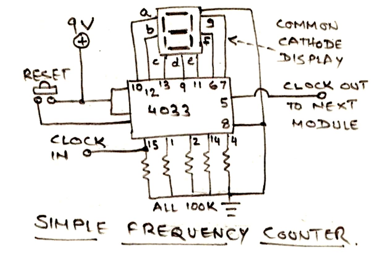
The circuit illustrated below is designed for measuring frequency in Hertz (Hz). It is straightforward to construct, utilizing a single IC 4033 and a common cathode display as the main components. For measuring higher frequencies, typically in the range...