
quick question about dimmers
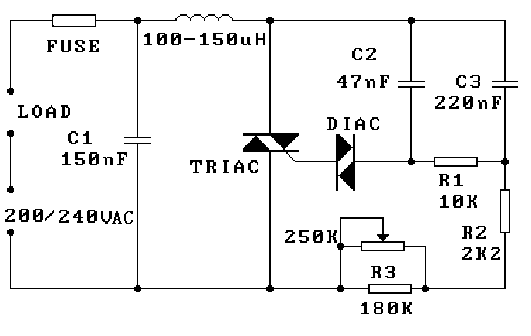
To achieve precise control over the light output of a bulb using two dimmers in series, it is essential to understand the operational characteristics of dimmers and how they interact in a circuit configuration. Typically, dimmers function by adjusting the phase of the AC voltage supplied to the load, which in this case is the bulb. When connecting two dimmers in series, it is crucial to ensure that both dimmers are compatible and rated for the same voltage and current specifications.
The first dimmer can be used to set a baseline light level, while the second dimmer can provide finer adjustments. This configuration allows for greater flexibility in controlling the brightness of the bulb. However, it is important to note that the total power rating of the two dimmers combined should not exceed the power rating of the bulb or the circuit.
For enhanced precision, the suggestion to include a second potentiometer in series with the control potentiometer is valid. This additional potentiometer, with a resistance value approximately one-tenth that of the main control potentiometer, functions as a vernier adjustment. This setup allows for minute adjustments to the overall brightness, providing a more refined control mechanism for the light output.
When implementing this configuration, careful consideration must be given to the wiring and connections to avoid any potential issues such as voltage drop or phase interference between the two dimmers. It is advisable to use quality components and ensure that all connections are secure and insulated to prevent any electrical hazards.
Furthermore, in the context of the school project, obtaining a DC power supply from a manufacturer in exchange for advertising could be beneficial. It would provide a stable power source for the project while also establishing a partnership that could enhance educational resources. Manufacturers that produce inverters for solar systems could also be approached for collaboration, as their products align with sustainability initiatives and could be relevant to the project objectives.
In summary, connecting two dimmers in series can provide enhanced control over light emission, and incorporating an additional potentiometer can further refine this control. Careful consideration of component specifications and circuit design will ensure a successful implementation for the school project.I want to know if I can connect 2 dimmers in series to control more preciselly the light of a bulb. I want to get a medium/high precission of light emission, for a school project. I wonder if you can get a manufacturer to lend you a DC power supply in exchange for advertising for them. Have literature available for your students. is one such comp any. They also make inverters for solar systems and that would be good advertising for them. make sure it is OK with the school. They are very nice supplies. The dimmers I`ve used have very good precision. If you need more, add a second pot in series with the control pot with a value of about 1/10th of the control pot`s. That will give a vernier type adjustment. 🔗 External reference
Related Circuits
The 1989 2.6 outside thermometer (Celsius) has malfunctioned and stopped displaying readings. A replacement unit was sourced from an eBay seller. The malfunctioning outdoor thermometer likely employs a thermistor or a similar temperature-sensing component to measure ambient temperature. In a...
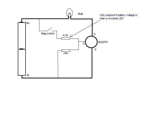
In this schematic provided by Jimmy M, will this circuit drain the batteries when the light is not in use? There is consideration for building a MOSFET circuit to be used in a compact application, where the original bulky...
This light dimmer control features active timing capacitor reset or AC line zero-crossing synchronization. The 13 additional components are common and cost less than $2. Performance at the low end is exceptionally smooth and snap-free, even better than the...
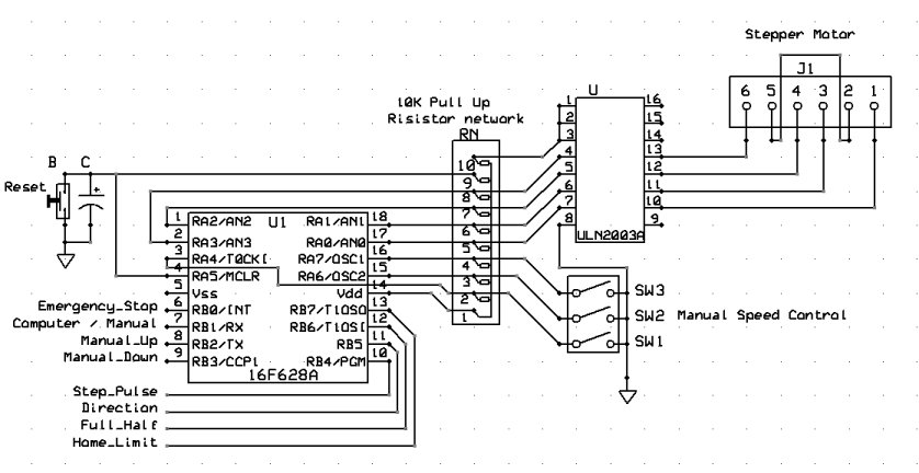
The inquiry was focused not only on power consumption but also on the observation that some stepper motors have more wires than the standard four, while others are classified as bipolar. Stepper motors are widely used in various applications due...
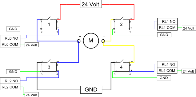
Eight solid-state relays (SSR) and an ADAM-4068 (Serial-I/O device) are utilized to wire a circuit for controlling a motor in a robotic application. The ADAM-6048 is a versatile device that facilitates control of digital inputs and outputs via RS-485...
The project involves the use of a Lattice isp2032VE110LT144 programmable logic chip, with a focus on integrating an LCD screen module. The development process included using MS Visual Basic for LCD control and the ispLever Navigator software for programming...