
R/C Thermal Peak Detection NiCd Charger
The charger circuit is designed to efficiently manage the charging of nickel-cadmium (NiCd) battery packs, specifically those consisting of 4 to 7 cells in series. This configuration allows for a flexible range of battery capacities, accommodating packs from 600mAh to 2Ah. The automatic initiation of the charging process upon connection of a battery pack enhances user convenience, as no manual intervention is required.
The core charging mechanism relies on a nearly constant current approach, which is adjustable to suit the specific requirements of the connected battery pack. This feature is critical in ensuring that the batteries are charged safely and effectively, preventing overcharging and potential damage. The termination of the charging process is intelligently managed by monitoring the temperature of the battery pack. As NiCd batteries reach full charge, they exhibit a slight increase in temperature; this characteristic is utilized to signal the charger to cease current flow, thereby safeguarding the battery's integrity.
An LED indicator is incorporated into the design to provide visual feedback regarding the charging status. When the charger is actively charging a battery pack, the LED illuminates, serving as an assurance to the user that the process is underway.
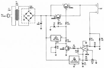
The operational backbone of the circuit is the comparator Z1A. This component plays a pivotal role in monitoring the voltage levels at its two inputs. The "+" input (pin 5) is connected to a reference voltage, while the "-" input (pin 6) receives the voltage from the battery pack. When the voltage at the "+" input exceeds that at the "-" input, Z1A outputs a high signal, indicating that charging should continue. Conversely, if the voltage at the "-" input rises sufficiently—typically due to the battery's temperature increase—the output of the comparator transitions to a low state, triggering the cessation of charging.
This simple yet effective design ensures that the charger operates within safe limits while providing the necessary functionality for charging NiCd packs, making it a reliable choice for users seeking an uncomplicated charging solution.The charger described in this article can charge packs of 4 to 7 cells with capacities ranging from 600mAh to 2Ah. The charger automatically begins charging when a pack is connected. It charges at a (nearly) constant current (adjustable), and terminates the charge when the pack begins to get warm (a NiCd pack begins to warm up when it has reached full charge).
An LED indicates that charging is in progress. The circuit for the charger (Figure 1) is simple. Z1A is a comparator which compares the voltage on its two inputs and produces a high output when the "+" input (pin 5) is higher than the "-" input (pin 6), and a low output otherwise. 🔗 External reference
Related Circuits
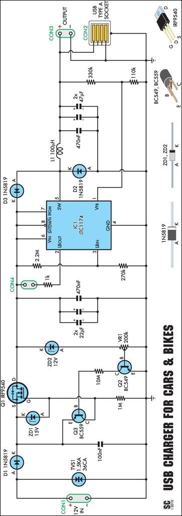
An efficient USB charger designed to operate from a 12V car battery, achieving up to 89% efficiency and capable of charging USB devices at currents up to 525mA. It does not drain the battery if left permanently connected, provided...
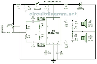
This is the circuit diagram of a USB-powered computer speaker, commonly referred to as multimedia speakers for PCs. The circuit features a single-chip design, operates on a low-voltage electrical power supply, is compatible with USB power from computers, includes...
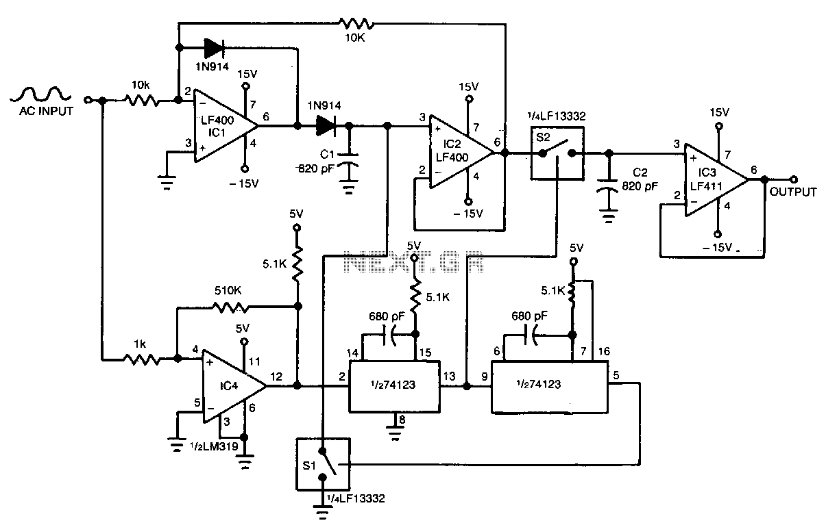
IC1 and IC2 form an inverting half-wave precision rectifier and peak detector circuit. Negative input signals that swing with peaks larger than the voltage on C1 cause this capacitor to charge to the new peak voltage. The capacitor retains...
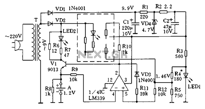
The circuit operates for 10 hours using constant current charging, providing convenience. The electricity from the secondary transformer T is stepped down, with the output directed through VD1 for rectification, followed by R1 and C1 for filtering. VD4 regulates...
The charger's output voltage is adjustable and regulated, featuring an adjustable constant-current charging circuit that is compatible with most NiCad batteries. It is capable of charging a single cell or multiple series-connected cells with a maximum voltage of 18V....

This application note explains how to implement a 2.1 (satellite/subwoofer) audio power-amplifier system with 2 x 2W and 1 x 7W of output power from a single 5V power supply. The described 2.1 audio power-amplifier system is designed to deliver...
Warning: include(partials/cookie-banner.php): Failed to open stream: Permission denied in /var/www/html/nextgr/view-circuit.php on line 713
Warning: include(): Failed opening 'partials/cookie-banner.php' for inclusion (include_path='.:/usr/share/php') in /var/www/html/nextgr/view-circuit.php on line 713