
Radio frequency Of Remote Control

The remote control circuit operates by transmitting radio frequency (RF) signals to communicate with various devices. At its core, the circuit typically comprises a transmitter and a receiver. The transmitter generates RF signals, which are modulated to convey specific commands, while the receiver interprets these signals to execute the desired actions on the controlled device.
Key components of the circuit include a transistor, which functions as a switch or amplifier, allowing for the modulation of the RF signal. The circuit may also incorporate resistors, capacitors, and inductors to form oscillators and filters that ensure the RF signal is stable and operates within the desired frequency range.
The transmitter section usually consists of an oscillator circuit that generates a high-frequency signal. This signal is then modulated using a method such as amplitude modulation (AM) or frequency modulation (FM) to encode the control commands. The modulated signal is amplified by the transistor before being sent out through an antenna.
On the receiving end, the receiver circuit captures the RF signals using an antenna and demodulates them to extract the control commands. This is typically achieved using another transistor configured as a demodulator, along with additional components to filter and amplify the received signal. The output of the receiver can then be connected to a microcontroller or relay, which executes the commands by controlling various devices, such as motors, lights, or other electronic systems.
Overall, this remote control circuit provides a versatile solution for wireless control applications, enabling users to operate devices from a distance with ease and convenience.This is a remote control Circuit that uses radio frequency electrical signal to control a variety of applications. Component: Transistor, .. 🔗 External reference
Related Circuits
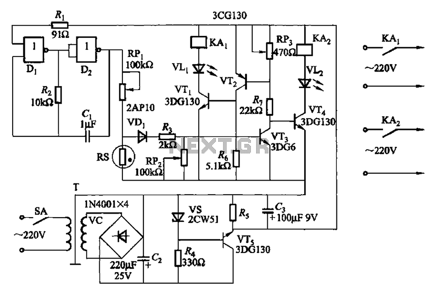
Two NAND gates (Di, Dz) and a resistor (Rz) along with capacitors (C1, etc.) form an RC self-excited multivibrator with an oscillation frequency of 2.5 Hz and an oscillation amplitude of 4 V. This circuit is used as a...

The generated alternating current (AC) at both ends of the voltage is adjusted after being rectified to supply the motor armature windings, allowing for speed adjustments of a 15W lamp. It is noteworthy that despite the freewheeling role of...
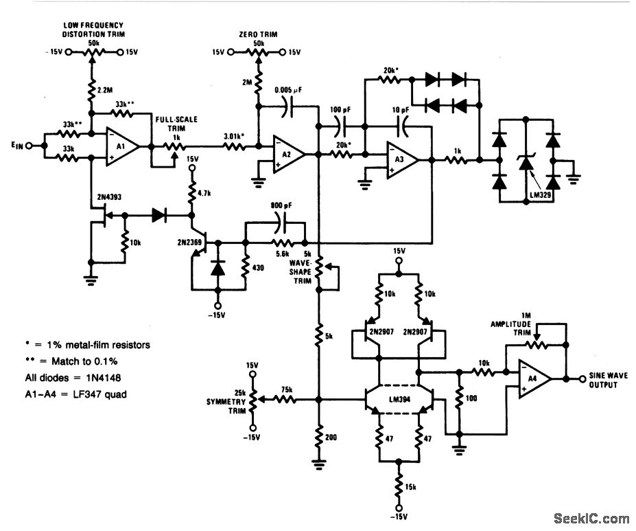
For a 0- to 10-V input, this circuit generates sine-wave outputs ranging from 1 Hz to 20 kHz, achieving linearity better than 0.2%. The distortion level is approximately 0.4%, and both the frequency and amplitude of the sine-wave output...
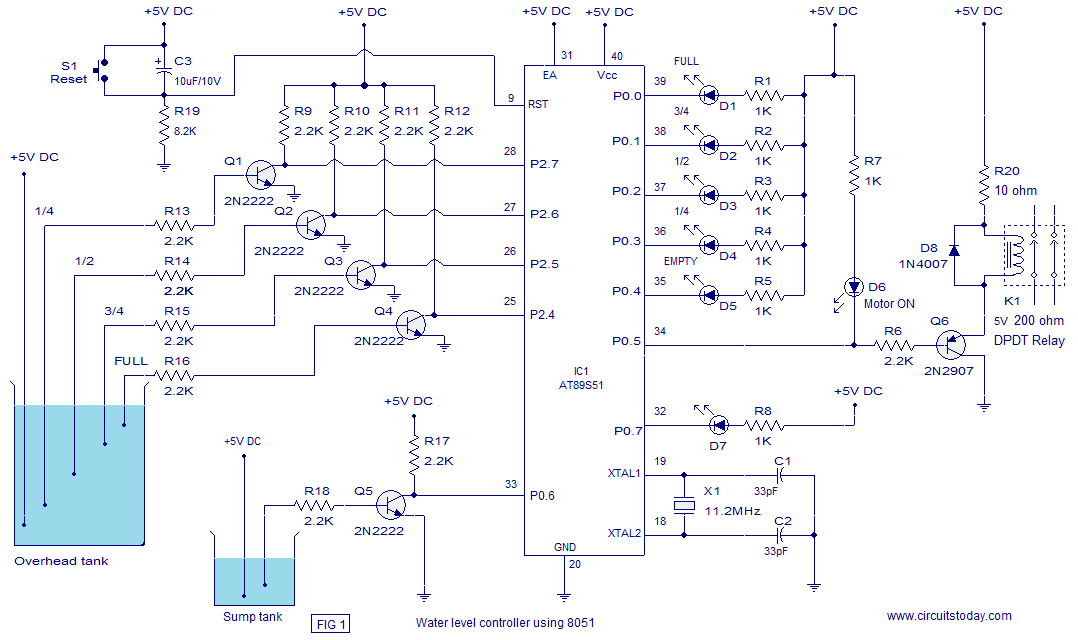
A water level controller based on the 8051 microcontroller is presented in this article. While numerous water level controller projects have been published on this website, this is the first one utilizing a microcontroller. The water level controller monitors...
This ZIP file contains information about building a small radio transmitter, which has a PCB 1.75" x 2.5" (45mm x 68 mm) and has a range of about 30 yards or so. The documentation with the circuit says the...
I found this circuit in my files. I don't know where it came from, but it looks like I photocopied it from somewhere years ago. I have been told that it came from "The Robot Builder's Bonanza", by Gordan...