
Stepper Motor Controller
The circuit described is a simple stepper motor controller designed to drive stepper motors using basic electronic components, making it an economical alternative to commercial solutions. The schematic typically includes a microcontroller or a simple logic circuit to generate the necessary control signals.
The core of the circuit usually consists of a H-bridge configuration, which allows for bi-directional control of the stepper motor. This configuration is often implemented using transistors or MOSFETs that switch the current through the motor coils in a specific sequence, enabling precise control over the motor's position and speed.
Power supply requirements are minimal, as the circuit can operate on standard voltage levels, often between 5V to 12V, depending on the specifications of the stepper motor being used. Resistors and capacitors may be included for signal conditioning and to protect the components from voltage spikes.
For adaptability to computer control, the circuit can interface with a microcontroller or a PC through a USB-to-serial converter or similar interface, allowing for programming and control via software. This setup enables users to implement various control algorithms, such as acceleration profiles or position feedback systems, enhancing the functionality of the stepper motor application.
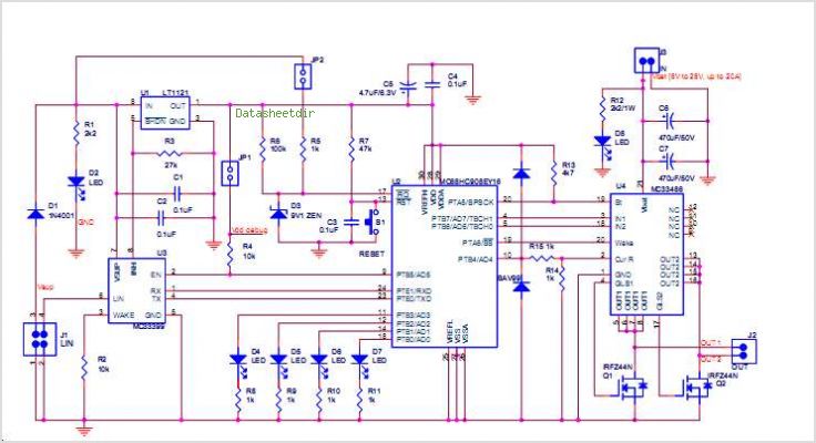
Overall, this stepper motor controller circuit represents a valuable resource for hobbyists and engineers looking to implement motor control solutions without incurring the costs associated with commercial integrated circuits. Its simplicity and adaptability make it suitable for a wide range of robotic and automated applications.I found this circuit in my files. I don`t know where it came from, but it looks like I photocopied it from somewhere years ago. I have been told that it came from "The Robot Builder`s Bonanza", by Gordan McComb. Anyway, I thought that it should be fairly useful, so I decided to post it here. The circuit is very simple and inexpensive. This is good thing because most commercial stepper motor controller ICs are quite expensive. This circuit is built from standard components and can easily be adapted to be controlled by a computer. 🔗 External reference
Related Circuits
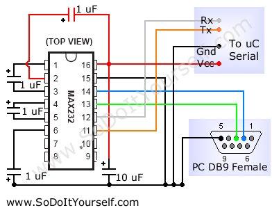
A device that provides a USB port is recognized as a "CP2103 USB to UART Bridge Controller" when connected to a Windows PC. According to the device documentation, it communicates in serial format at 38400 bps. The USB pinout...

This simple pulse width modulation (PWM) DC motor control addresses common issues by regulating motor speed through the application of short pulses. The duration of these pulses is varied to adjust the motor speed; longer pulses result in faster...
.jpg)
The project outlines a method to add a cost-effective remote doorbell to an existing household doorbell system, particularly useful for individuals who may not hear the doorbell when in the basement. The household doorbell operates on a continuous 24VAC...
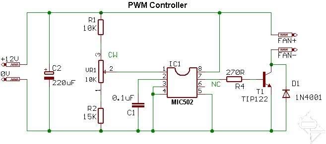
This circuit diagram illustrates the design for each individual channel. A modification was made by replacing the 0.1 µF timing capacitor with a 100 pF capacitor to enhance performance. The original 0.1 µF capacitor caused the fans to produce...
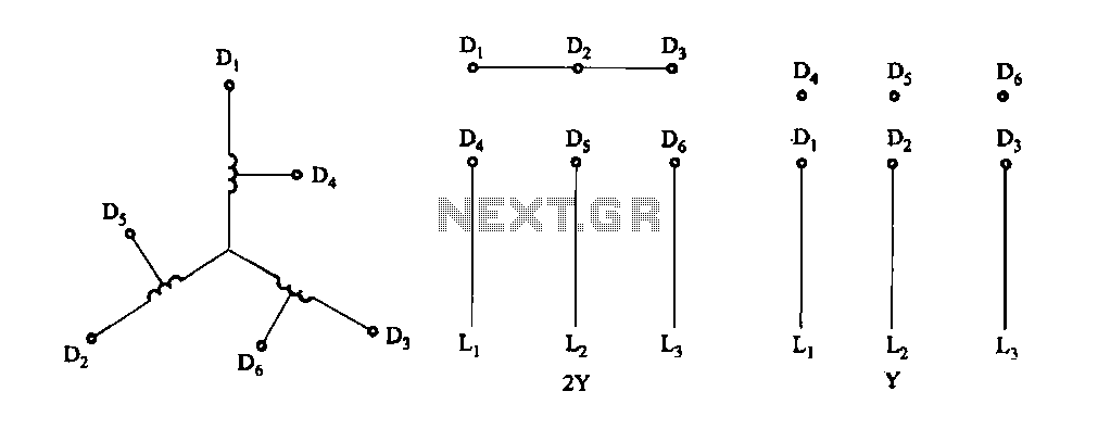
Figure 3-100 illustrates the lead wiring diagram for the stator windings of a two-speed motor configured in a 2Y/Y connection. The two-speed motor stator wiring diagram depicted in Figure 3-100 provides a clear representation of the electrical connections required for...
The WS2512-TR1G is a Wide-band Code Division Multiple Access (WCDMA) Power Amplifier (PA) designed as a fully matched 10-pin surface mount module, specifically developed for WCDMA handset applications. This power amplifier module operates within a frequency range of 1920-1980...