
Radio Modem Circuit
The radio modem operates by facilitating packet data communication over amateur radio frequencies. It is designed to interface seamlessly with various amateur radio transceivers, allowing for efficient data transmission and reception. The modem typically utilizes a microcontroller or digital signal processor (DSP) to manage the encoding and decoding of packet data, ensuring reliable communication.
The power requirements of the modem are met through the data and control lines, which simplifies the overall design and reduces the need for external power supplies. This feature is particularly advantageous in portable or field applications where minimizing equipment weight and complexity is crucial.
Key components of the radio modem may include an RF front end for signal amplification and filtering, a microcontroller for processing data, and a user interface for configuration and monitoring. The modem may also incorporate error detection and correction algorithms to enhance data integrity during transmission.
Connection to the amateur radio transceiver is typically achieved through standard interface protocols, such as RS-232 or USB, allowing for compatibility with a wide range of devices. The modem's design may also include indicator LEDs to provide visual feedback on operational status, such as power, data transmission, and error conditions.
Overall, this radio modem represents a compact and efficient solution for amateur radio enthusiasts looking to engage in packet radio communications, offering ease of use and integration into existing radio setups.This radio modem is popular for amateur radio packet application. This radio modem is powered by the data and control lines, so it need no additional power. 🔗 External reference
Related Circuits
When the lights of an oncoming car are detected by the photo-transistor Q1, the circuit activates. Sensitivity is adjusted by the 22-megohm resistor, R5, to approximately half a foot-candle. The relay employed has a 12-volt, 0.3A coil. The L14C1...
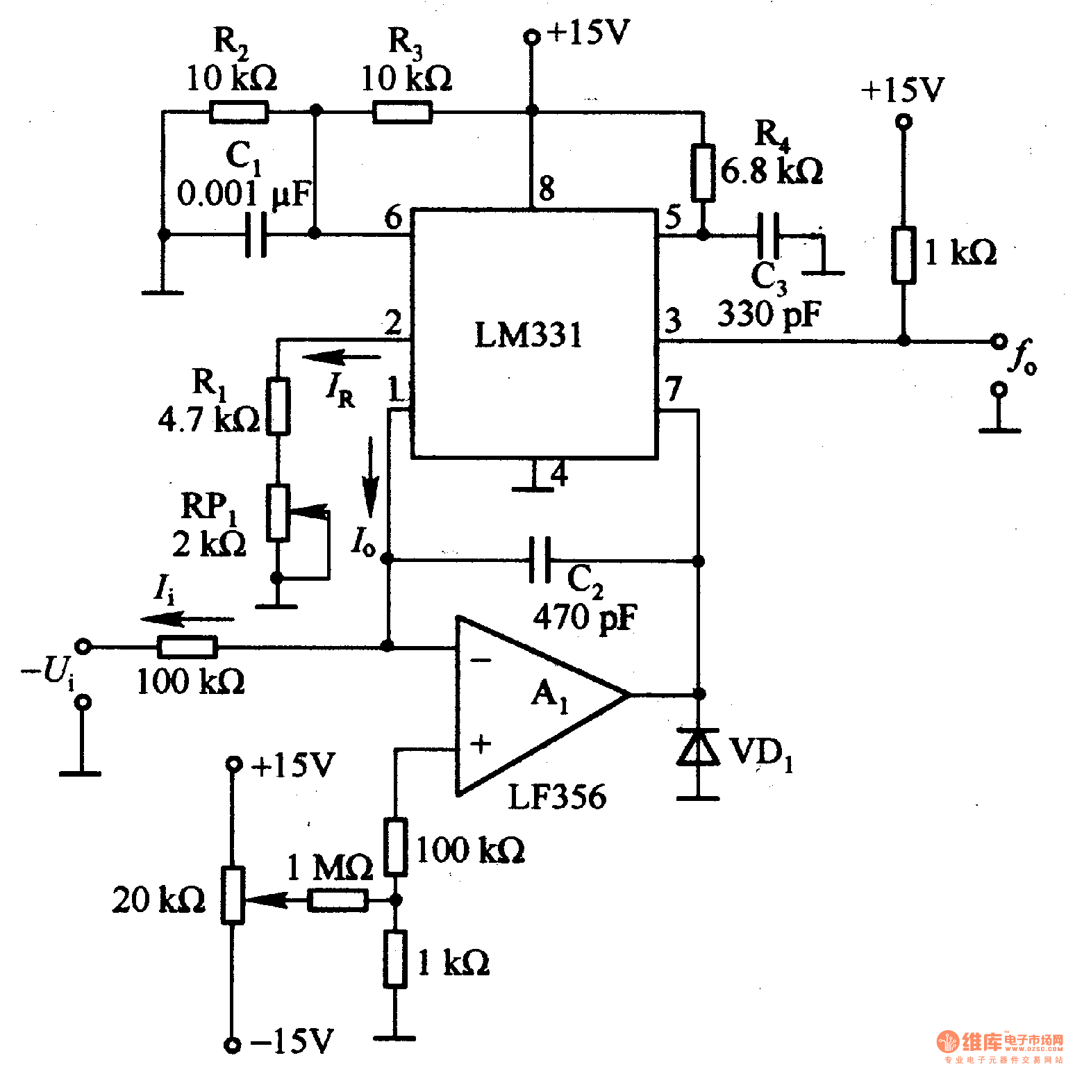
The LM331 is a single voltage-to-frequency conversion integrated circuit (IC) that includes a 1.9 V reference voltage, a current switch, a comparator, and a flip-flop. To expand its operational range, an A1 operational amplifier is added to the circuit....
The LM358 consists of two independent, high-gain operational amplifiers in a single package. An important feature of this integrated circuit (IC) is that it does not require separate power supplies for the operation of each comparator, accommodating a wide...
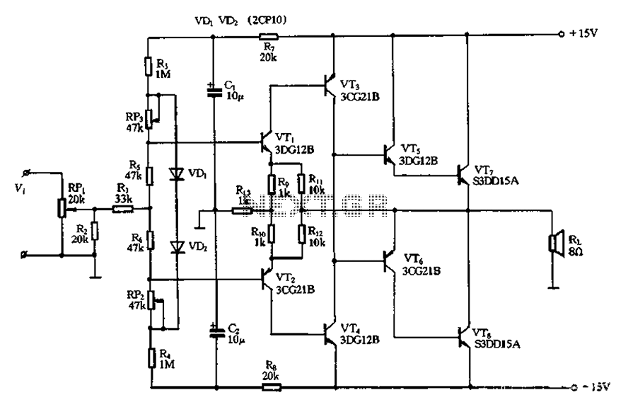
The circuit utilizes diode VDi, f Pooh to stabilize the base bias of transistors VTi and VT2, ensuring a more stable quiescent point when the supply voltage is within a specific range. In the event of temperature fluctuations, the...
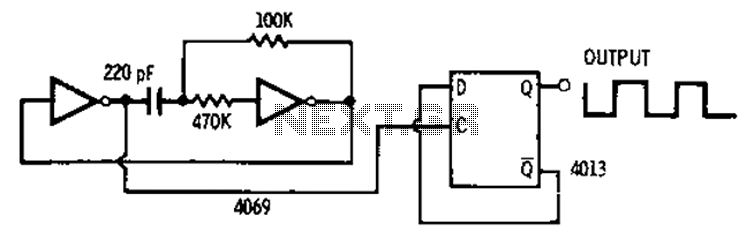
The 4013 pairs of D-type flip-flops in the astable multivibrator configuration are utilized as a binary divider output, generating an output frequency that is symmetrical, with a duty cycle of 50%. The 4013 integrated circuit contains two D-type flip-flops that...
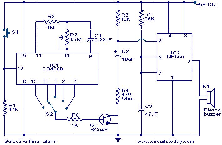
The following circuit illustrates a Selective Timer Alarm Circuit based on the 4060 Integrated Circuit (IC). Features include an automatic turn-off mechanism for the alarm after a specified duration. The Selective Timer Alarm Circuit utilizes the 4060 IC, which serves...