
raspberry pi thermostat hookups
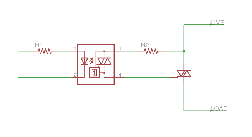
The schematic for this setup would include a Raspberry Pi, three opto-coupled TRIACs, and the associated resistors R1 and R2 for each circuit. The live 24V AC wire should be fed into each TRIAC circuit, with the control wires for the HVAC components connected to the load side of each TRIAC. The opto-couplers should be connected to the GPIO pins of the Raspberry Pi to allow for digital control.
Each opto-coupler's LED side is connected to the GPIO pin through a current-limiting resistor (R1), ensuring that the current does not exceed the LED's specifications. The TRIACs are connected in such a way that when an appropriate voltage is applied to the gate of the larger TRIAC through the smaller opto-coupled TRIAC, it allows current to flow to the HVAC component. Resistor R2 is necessary to protect the smaller TRIAC from excessive current once it is activated.
It is essential to observe the correct orientation of the AC wires to prevent malfunction. The system should be tested with the HVAC components to verify that they respond correctly to the Raspberry Pi's GPIO signals, ensuring reliable operation of the heating, cooling, and ventilation systems in the home. Proper safety precautions should be taken when working with AC wiring to avoid hazards associated with electrical shock or equipment damage.How to make the hardware connections between the Raspberry Pi and the house wiring. Check out this post if you want a PCB that does the connections for you. In my house (and the vast majority of others) the thermostat wiring runs at 24V AC. There`s a live wire (or two, depending on the setup) coming into the thermostat, and several others leaving to control the different components of the HVAC system. The thermostat`s job is to close the circuit between the live wire and the appropriate control wire based on the temperature. A relay is an easy way to do it, but I find relay`s cumbersome with their (usually) breadboard unfriendly pin layout and larger-than-can-be-supplied-by-gpio switching current requirements.
I have found, in my opinion, a much better way of switching AC current: the TRIAC. If you`ve ever used a MOSFET for DC current switching, a TRIAC is similar in application (but not physics), only for AC current. There are some important differences, however. Probably the biggest difference is that once a TRIAC is activated, it will not deactivate until the current through it drops below some small threshold current, and I`m not talking about the gate current.
Because of this the TRIAC is pretty useless for DC since once there`s current flowing it will never drop (unless you have another switch somewhere, which kinda defeats the purpose, or the battery dies. ). In AC, the voltage (and hence current) will go to zero twice every cycle, so shutting the thing off is not an issue.
An important side effect of this is that it`s impossible to switch a TRIAC faster than the frequency of the AC line it`s connected to, so you can forget about using it for PWM. But you CAN control when in the cycle it turns on to control the average current flow available to whatever it`s connected to, and this is exactly what light dimmer switches do.
The 3 pin device is connected in line with the wire you want to switch, and a current is applied to the gate to turn the switch on. But TRIAC`s are a little more complicated than MOSFET`s. If you want to switch anyappreciableamount of current (I was verysurprisedto learn that my HVAC control lines draw nearly 1.
5A at 24V AC) you probably can`t switch the TRIAC directly with a gpio. You need a second, smaller TRIAC as an intermediary. But don`t fret, it`s a very simple circuit. I use an opto-coupled TRIAC as my small one for an added layer of isolation between the gpio and what I`m switching. Plus, it makes turning on and off the switch as easy as turning on and off an LED. All that needs to be done is to apply a voltage across the LED of the opto through the current limiting resistor R1.
The two TRIAC`s are connected together as shown in the schematic, with the smaller one connecting the live wire to the gate of the larger TRIAC. Since the smaller one is actually quite small, R2 is necessary to limit the amount of current that would rush through it once it`s activated.
It is also important to get the order of the AC wires correct. Just because it`s AC doesn`t mean the wires are interchangeable! Getting back to the thermostat, my house has 3 control wires that I`m interested in: the blower fan, heater, and air conditioner. That means I need 3 of these TRIAC circuits. The live 24V AC wire feeds into each of them, and the control wire goes on the load side. Connect the 3 opto`s to 3 gpio`s on the Raspberry Pi and viola! I have control. 🔗 External reference
Related Circuits
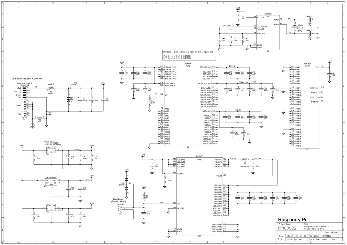
This post outlines the significant modifications implemented in the latest revision of the board. It is important to note that, while the option to incorporate additional signals into the expansion connector has not yet been utilized, developers of expansion...

The thermostat electric circuit operates as depicted in the figure. It has three settings: off, low power (Lo), and high power (Peru HL). When the DIP switch SA is set to the Lo position, 220V AC is directed through...
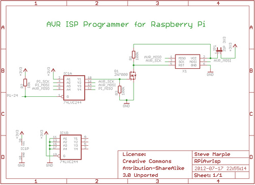
As a fully-featured Linux computer, many external programmers can be used with the Raspberry Pi to program the Atmel AVR range of microprocessors. It is also possible to utilize the general-purpose input/output lines (GPIOs) found on the Raspberry Pi...

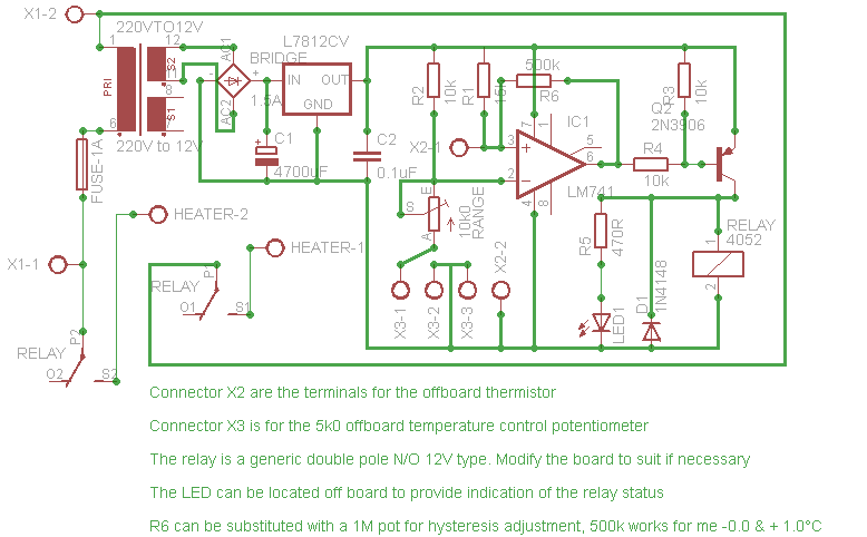
Here is a simple thermostat circuit that can be used to control a relay and supply power to a small space heater through the relay contacts. The relay contacts should be rated above the current requirements for the heater....
The heating element is connected in series with two back-to-back 16 amp silicon-controlled rectifiers (SCRs), which are controlled by a small pulse transformer. This pulse transformer features three identical windings: two are dedicated to providing trigger pulses to the...
Affordable, straightforward, and precise thermostat circuits with instructions. The thermostat circuit is designed to provide a cost-effective and reliable solution for temperature control applications. It typically utilizes a temperature sensor, such as a thermistor or a thermocouple, to monitor the...