
RC (Remote Control) Switch
The described circuit employs a TLC555 timer configured as a monostable multivibrator to control the switching mechanism for an RC model. The input servo signal, which is variable in duration, is conditioned through buffering and differentiation to create a clean trigger pulse for the timer. The timer's output pulse duration is adjustable based on external resistors and capacitors, allowing for fine-tuning of the switching event. The integration of a D flip-flop ensures stable output even in the presence of signal variations, while the hysteresis feedback mechanism prevents rapid toggling of the output state, enhancing reliability. The circuit's design accommodates various output configurations through jumper selection, facilitating adaptability to different applications. Additionally, the inclusion of a protective diode for inductive loads ensures that the circuit can safely control devices such as pneumatic valves, making it versatile for various RC model applications. Overall, this schematic represents an efficient and reliable solution for implementing switching functions in remote control models.It is sometimes necessary for an RC (remote control) model to contain some kind of switching functionality. Some things that come to mind are lights on a model boat, or the folding away of the undercarriage of an aeroplane, etc.
A standard solution employs a servo, which then actually operates the switch. Separate modules are also available, which may or may not contain a relay. A device with such functionality is eminently suitable for building yourself. The schematic shows that it can be easily realised with a few standard components. The servo signal, which consists of pulses from 1 to 2 ms duration, depending on the desired position, enters the circuit via pin 1 of connector K1. Two buffers from IC2 provide the necessary buffering after which the signal is differentiated by C2. This has the effect that at each rising edge a negative start signal is presented to pin 2 of IC1. D1 and R4 make sure that at the falling edge the voltage at pin 2 of IC2 does not become too high. IC1 (TLC555) is an old faithful in a CMOS version. A standard version (such as the NE555) works just as well, but this IC draws an unnecessarily high current, while we strive to keep the current consumption as low as possible in the model.
The aforementioned 555 is configured as a one-shot. The pulse-duration depends on the combination of R2/C1. Lowering the voltage on pin 5 also affects the time. This results in reducing the length of the pulse. In this circuit the pulse at the output of IC will last just over 1. 5 ms when T1 does not conduct. When T1 does conduct, the duration will be a little shorter than 1. 5 ms. We will explain the purpose of this a little later on. Via IC2. C, the fixed-length pulse is, presented to the clock input of a D-flip-flop. As a consequence, the flip-flip will remember the state of the input (servo signal). The result is that when the servo-pulse is longer than the pulse form the 555, output Q will be high, otherwise the output will be low. It is possible, in practice, that the servo signal is nearly the same length as the output from the 555.
A small amount of variation in the servo signal could therefore easily cause the output to chatter`, that is, the output could be high at one time and low the next. To prevent this chatter there is feedback in the form of R1, R3 and T1. This circuit makes sure that when the flip-flip has decided that the servo-pulse is longer than the 555`s pulse (and signals this by making output Q high), the pulse duration from the 555 is made a little shorter.
The length of the servo-signal will now have to be reduced by a reasonable amount before the servo-pulse becomes shorter than the 555`s pulse. The moment this happens, T1 will stop conducting and the mono-stable time will become a little longer.
The servo-pulse will now have to be longer by a reasonable amount before the flip-flip changes back again. This principle is called hysteresis. Jumper JP1 lets you choose between the normal or inverted output signals. Buffers IC2. D through to IC2. F together with R5 drive output transistor T2, which in turn drives the output. Note that the load may draw a maximum current of 100 mA. Diode D2 has been added so that inductive loads can be switched as well (for example, electrically operated pneu-matic valves).
🔗 External reference
Related Circuits
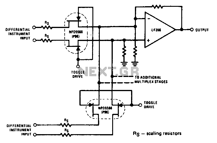
The NPD5566 monolithic dual is utilized in differential multiplex applications where the Rds(ON) should be closely matched. The monolithic dual tracks at better than ±1% over a wide temperature range of -25°C to +125°C, making it an unusual yet...
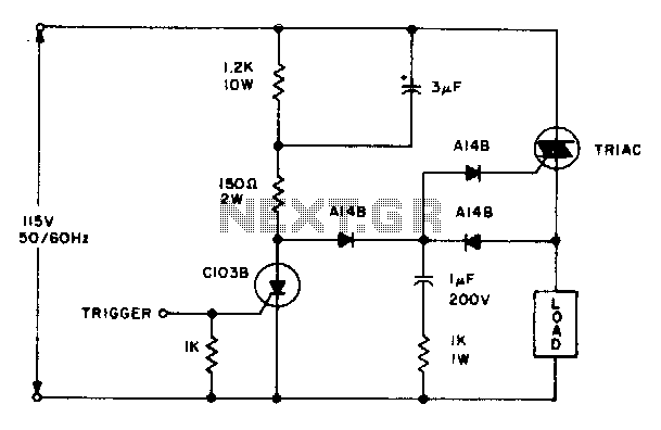
The triac will be activated at the beginning of the positive half cycle due to the current flowing through the 3 µF capacitor, provided that the C103 SCR is in the off state. The load voltage subsequently charges the...
This circuit is a constant current protection type that limits the output current to a specific value in cases of over-current and short-circuit conditions. When the output current exceeds this limit, the output voltage decreases. The CW200 power management...
This is a high-frequency switch circuit. This circuit utilizes the 2N4391 transistor. When in the off state, it provides a high off-impedance of less than 0.2 pF and exhibits a low on-resistance. The high-frequency switch circuit designed with the 2N4391...
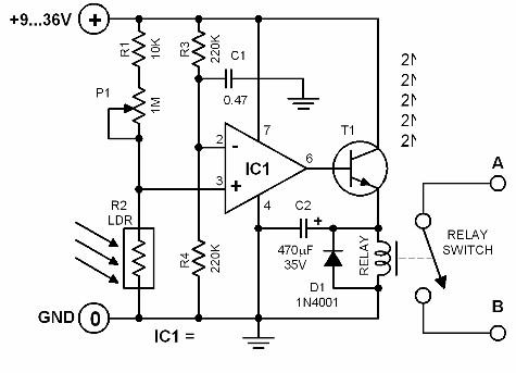
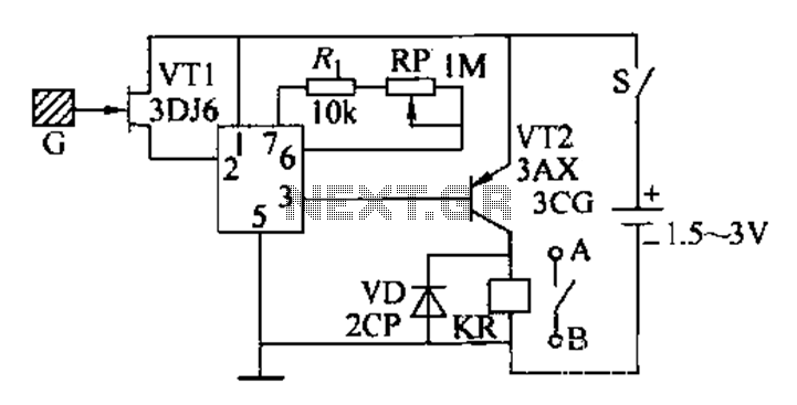
The brightness of the surrounding light controls the function of this circuit. The light sensor used in this circuit is a light-dependent resistor (LDR). This LDR is connected to the non-inverting input of the 741 op-amp IC. Once the...
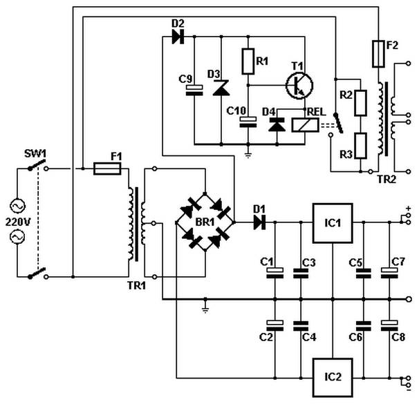
Soft power for a large transformer is implemented by using a series resistance of 100 ohms at 10 watts, or alternatively, two resistors of 47 ohms at 5 watts each in the primary circuit. The resistance is bypassed by...
Warning: include(partials/cookie-banner.php): Failed to open stream: Permission denied in /var/www/html/nextgr/view-circuit.php on line 713
Warning: include(): Failed opening 'partials/cookie-banner.php' for inclusion (include_path='.:/usr/share/php') in /var/www/html/nextgr/view-circuit.php on line 713