
RCA BC-224-A - the First BC-348

The BC-348 series aircraft receivers represent a significant advancement in aviation communication technology during the mid-20th century. These receivers were designed with a focus on reliability and performance under challenging conditions, such as high altitudes where temperature and pressure variations could affect radio operation. The inclusion of a heater switch for the local oscillator was a critical innovation, ensuring that the oscillator maintained its stability and frequency accuracy, which is paramount for effective communication in flight.
The design of the BC-348 series incorporated both legacy elements and modern enhancements, making it a versatile choice for various aircraft applications. The layout of the controls was user-friendly, allowing pilots and operators to adjust settings quickly and efficiently, even in the demanding environment of an aircraft cockpit. The thoughtful integration of a transmission line for antenna connections reflects an understanding of practical installation challenges in diverse aircraft configurations.
Furthermore, the use of standardized power plugs facilitated easier maintenance and replacement, ensuring that the receivers could be serviced without specialized tools or components. The shock mount design, while differing in depth from later models, maintained compatibility with existing installations, which was crucial for operational continuity.
Overall, the BC-348 series, along with its associated transmitters, played a vital role in enhancing communication capabilities for military and civilian aircraft alike, paving the way for future advancements in aviation electronics. The combination of innovative design, practical features, and reliable performance established the BC-348 as a cornerstone in the evolution of aircraft radio technology.The mid to late 1930s reflected a curious mixture of old and new thinking in aircraft radios, led by brilliant engineers in such companies as Aircraft Radio Corporation and RCA. The example below should endear itself to every radio amateur growing up in the 1940s or 1950s, because it was the first of the BC-348 series of aircraft receivers.
A clos e look at its front panel will reveal the same controls that are on all the later BC-224/348s, with the addition of a "heater" switch that provided power to the thermostatically regulated local ("heterodyne") oscillator compartment to provide stability at high altitudes, and some relocation from the more familiar positions of the others. (The BC-348-J, N, and Q also deleted the antenna alignment knob, of course. ) This innovative receiver has a circuit diagram that looks very similar to its later counterparts, as well.
There was a curious inclusion of a short transmission line between the left and right side of the receiver along the bottom edge of the front panel, presumably to make antenna connections easier on some aircraft installations. A short wire from the "A" terminal on the left to an inexplicaby different shaped terminal 45 ° downward from it was required to connect the transmission line.
The familiar PL-Q103 and PL-P103 eight pin Jones style power plugs were identical to the later models, and though the FT-154 shock mount did not have the same depth as the later FT-154-*, it appears identical to the casual glance. Installed in a typical setting, a BC-224-A (above) in NASM`s unrestored O-47A observation aircraft shows its age, but also the ambience of an operational aircraft communications receiver.
The tuning knob has suffered from deterioration of its paint in the storage environment for so many years, but also does not match the one in the manual, which looks exactly like all the tuning knobs on the BC-348 series. The set below going into the "flight deck" was unmolested in the post-war rush by many radio amateurs to personalize their military sets, which produced every shade of paint and modification under the sun.
I have another example of a BC-224-A (what I would charitably have to call a parts set) in which someone had mounted miniature tubes and replaced the front panel with a carefully machined 19" rack panel! This relatively pristine receiver has an original dynamotor from an altogether too generous friend that was more akin to the BC-312/342 approach, being mounted in a stainless steel box that occupied almost 1/8 of the receiver cabinet volume.
Normal output under load was on the order of 206 volts - a lower voltage than used for many sets of its era, and one that promoted lower noise and longer tube life. The traditional post-1935 liason transmitter match for this receiver was the BC-AA-191, the combination designated the SCR-187 and detailed more fully here.
In some aircraft, the lower powered BC-307-A transmitter was used (shown here ), the combination designated the SCR-238. 🔗 External reference
Related Circuits
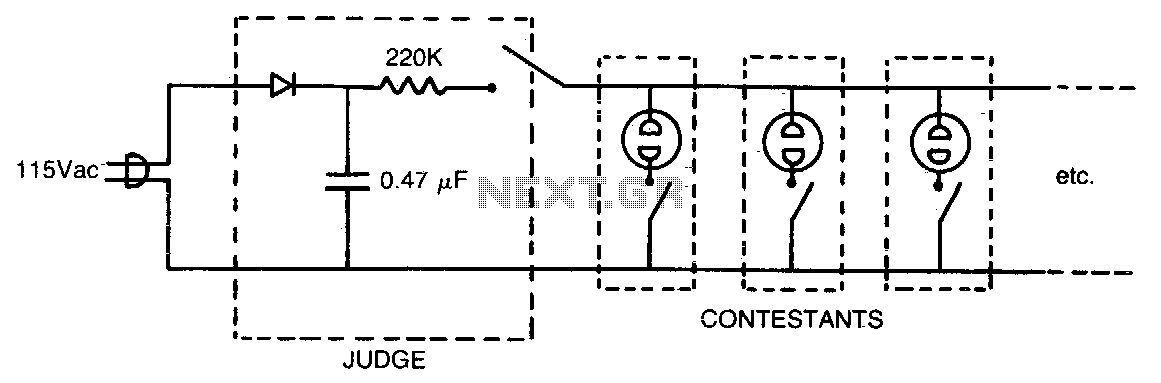
This circuit is designed for use in a question-and-answer party game. The first button pressed ionizes a neon bulb, causing the DC voltage across the parallel-connected neon bulbs (representing other contestants) to drop below the ionization threshold, thereby clearly...
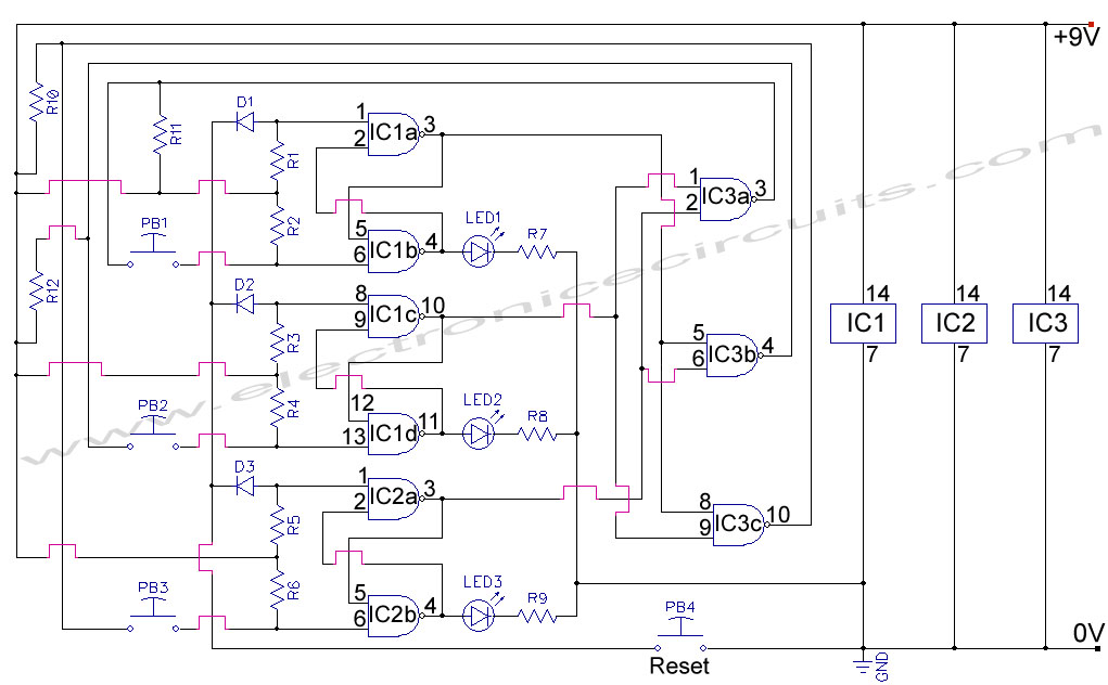
The circuit below turns on a light corresponding to the first of several buttons pressed in a "Who's First" game. Three stages are shown but the circuit can be extended to include any number of buttons and lamps. Three...
First Response Monitor, Input Selector, Game Circuit. This circuit is utilized for first response applications as it aids in monitoring various responses in games. The First Response Monitor circuit is designed to facilitate real-time monitoring and selection of input signals...

A simple supercapacitor charger electronic project can be designed using the LTC3625 integrated circuit (IC) from Linear Technology. This circuit is capable of charging two supercapacitors in series to a fixed output voltage of either 4.8V/5.3V or 4V/4.5V, which...

The circuit activates a light corresponding to the first button pressed in a "Who's First" game. Three stages are illustrated, but the circuit can be expanded to accommodate any number of buttons and lamps. The described circuit operates as a...
A pair of cross-coupled SCRs can be utilized to create a first-response monitor circuit, as illustrated in the schematic diagram below. The first-response circuit is... In the context of electronic monitoring systems, a first-response monitor circuit employing cross-coupled Silicon Controlled...