
Reaction Timer
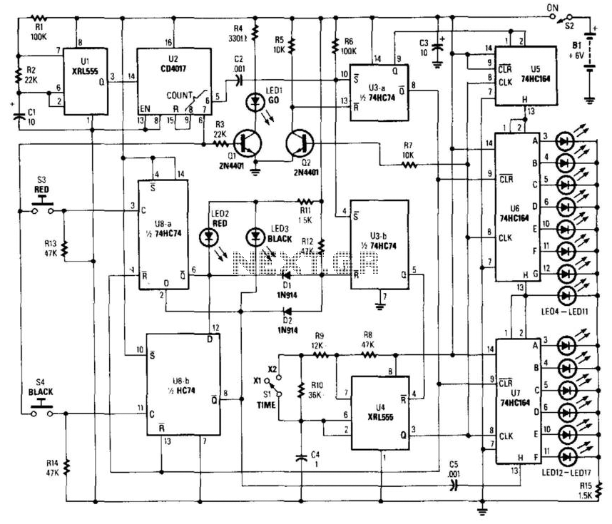
The circuit design incorporates a primary timer configured to generate a series of pulses at a frequency of 200 Hz (5 ms period). This timer is crucial for controlling the timing of the pulse outputs that are fed into a shift register. The shift register is responsible for capturing these pulses and subsequently driving an LED display, where each pulse corresponds to a state change in the LEDs.
An auxiliary timer functions independently to produce a pulse every second, which serves to activate a "go" LED. This LED signals the players to prepare for the reaction test. When the go signal is indicated, players are prompted to press their designated buttons (S3 for player one and S4 for player two). The circuit is designed to measure the time taken for each player to react and press their button after the go signal is activated.
The reaction time is quantified by monitoring the duration from the activation of the go signal until the button press occurs. This time value is then represented visually on a series of LEDs ranging from LED 4 to LED 17. Each LED corresponds to a specific range of reaction times, allowing for a quick visual assessment of performance.
After a duration of six seconds, the entire sequence resets, readying the circuit for another round of play. This cyclical operation enables continuous interaction, making the circuit suitable for competitive environments. Overall, the design effectively combines timing mechanisms and visual feedback to create an engaging user experience. This circuit uses a timer to generate pulses at a 5-ms clock rate. The pulses are shifted into the shift register, one at a time, lighting an LED. An auxiliary timer that generates one pulse per second is used to generate timing to activate the "go" LED and start the 5 ms pulses clocking into the registers. At the go signal each player presses his buttons (S3 or S4). The delay (reaction time) is read out on LED 4 to LED 17; after six seconds, the sequence repeats. 🔗 External reference
Related Circuits

This circuit is a temperature-controlled version of Repeating Timer No. 3. The light-dependent resistor has been replaced by a temperature-dependent resistor, or thermistor. A small preset potentiometer allows the user to select the temperature threshold above which the timer...
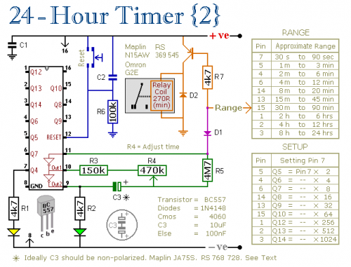
A pair of multi-range timers that provide timing periods of up to 24 hours and beyond. Both timers are fundamentally similar, with the primary distinction being that Version 1 energizes the relay when the time expires, while Version 2...
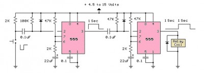
The LM555 timer circuit is similar to the previous design but incorporates two stages, allowing for control over both the pulse width and the delay. The LM555 timer is a versatile integrated circuit widely used in various timer, delay, pulse...
Pulse Generator kit will generate a frequency in KHz which can form a good test gear project. This kit is based on the classic LM555 timer IC. Input - 12 VDC Max @ 40 mA. Range - jumper selectable...
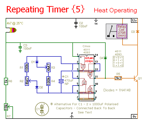
This timer circuit operates only when the temperature exceeds a predetermined level. An alternative version, known as Repeating Timer No. 6, functions while the temperature is below this preset level. The resistor R7 is used to set the temperature...
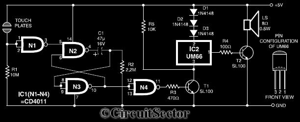
This circuit diagram illustrates a touch-sensitive musical bell based on the UM66 melody generator IC. The design incorporates a CMOS IC CD4011 and features a pair of touch plates. When these plates are briefly bridged by a hand, the...
Warning: include(partials/cookie-banner.php): Failed to open stream: Permission denied in /var/www/html/nextgr/view-circuit.php on line 713
Warning: include(): Failed opening 'partials/cookie-banner.php' for inclusion (include_path='.:/usr/share/php') in /var/www/html/nextgr/view-circuit.php on line 713