
Repeating Timer 5
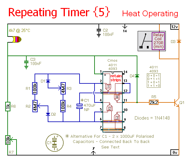
The circuit operates by utilizing an Astable Multivibrator configuration, where capacitive and resistive components define the timing intervals. The thermistor's resistance varies with temperature, altering the voltage at pin 1 of the timer IC. When the voltage exceeds a threshold determined by the resistors R1 and R2, the output state changes, activating the relay. The relay's operation is critical for controlling external devices, but care must be taken to ensure isolation from high-voltage components. To facilitate the desired timing functionality, the values of C1, R1, R2, R3, R4, and R6 can be adjusted to meet specific application requirements. The use of a non-polarized capacitor is essential in this design due to the alternating current characteristics of the timing circuit. The implementation of a thermistor in a controlled environment enhances sensitivity while minimizing the effects of transient temperature fluctuations. Overall, this timer circuit provides a versatile solution for temperature-dependent applications, with adjustable timing capabilities and a robust design suitable for various operational conditions.This timer circuit will only run when the temperature rises above a preset level. There`s an alternative version - Repeating Timer No. 6 - that only works while the temperature is below the preset level. R7 lets you set the temperature. The value of the thermistor is not critical. The important thing is the voltage on pin 1. Any value thermistor sh ould work satisfactorily. But you may need to change the value of R7 - to achieve the desired range of adjustment. The circuit is basically an Astable Oscillator. And the output times depend on the value of C1 - and the speed at which it charges and discharges through the resistor network. The length of time the relay remains energized is controlled by R1 & R2. And the length of the time it remains de-energized is controlled by R3 & R4. The fixed resistors set the minimum period lengths - and the maximum period lengths are set by R2 & R3.
With the component values shown - both periods are adjustable from about 1 to 30 minutes. You can change the component values to suit your own requirements. If your time periods don`t need to be too precise - and more-or-less is close enough - you can leave out the pots altogether - and simply rely on R1 & R4 to set the times. Owing to manufacturing tolerances - the precise length of the time periods available depends on the characteristics of the actual components you`ve used - and a 4093 will produce longer time periods than a 4011.
Do not use the "on-board" relay to switch mains voltage. The board`s layout does not offer sufficient isolation between the relay contacts and the low-voltage components. If you want to switch mains voltage - mount a suitably rated relay somewhere safe - Away From The Board.
I`ve used a SPCO/SPDT relay - but you can use a multi-pole relay if it suits your application. When the oscillator is running - the polarity of the charge on C1 keeps reversing. So C1 needs to be non-polarised. However - you can simulate a non-polarised 470uF capacitor by connecting two 1000uF polarised capacitors back to back - as shown. How and why this works is explained in the Detailed Circuit Because non-polarised capacitors aren`t widely available - the prototype was built using two polarised capacitors.
Roughly speaking - the operating temperature will adjust from about 5 C to 75 C (41 F to 167 F). However - this wide range makes the adjustment coarse. You can improve control by reducing the value of the pot and increasing the value of R6. Use R6 to take you close to the desired temperature - and use the reduced value pot to make the fine adjustment. Setting the operating temperature is best carried out "in situ" using trial-and-error. If the timer starts at too low a temperature - turn R7 a little to the right. If it starts at too high a temperature - turn R7 a little to the left. The following readings will give you some idea of what to expect. They are taken from the prototype. They apply to the Cmos 4011. And they were made using a cheap digital multimeter and a cheap thermometer. They are intended for guidance only. You should NOT expect to get identical readings. My thermistor measured 4. 45K at 25 C (77 F). My supply voltage measured 12v4. And the Pin 1 switching point was measured at just over 6v9. With R7 set to 5k - the timer worked at temperatures above about 21. 5 C (71 F). The mass of the thermistor is small - and it will react quickly to changes in temperature. This makes it sensitive to thermal currents. One solution is to create an enclosed environment - where the thermistor is protected from momentary draughts - but can still respond to slower changes in the overall ambient temperature.
The timer is designed for a 12-volt power supply. However - it will work at anything from 5 to 15-volts. All you need do is select a relay with a coil voltage that suits your supply. I used a single pole relay in the prototype - but you can use a multi-pole relay if it suits you 🔗 External reference
Related Circuits
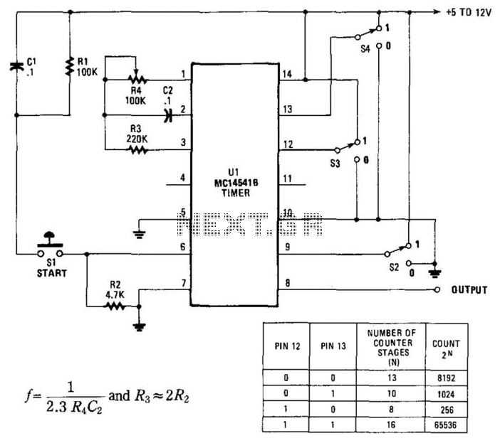
By utilizing an RC oscillator and a programmable divider, this counter can operate for extended periods. The interval oscillator functions at a frequency determined by specific component values: for instance, with R1 = 390 kΩ and C2 = 10...
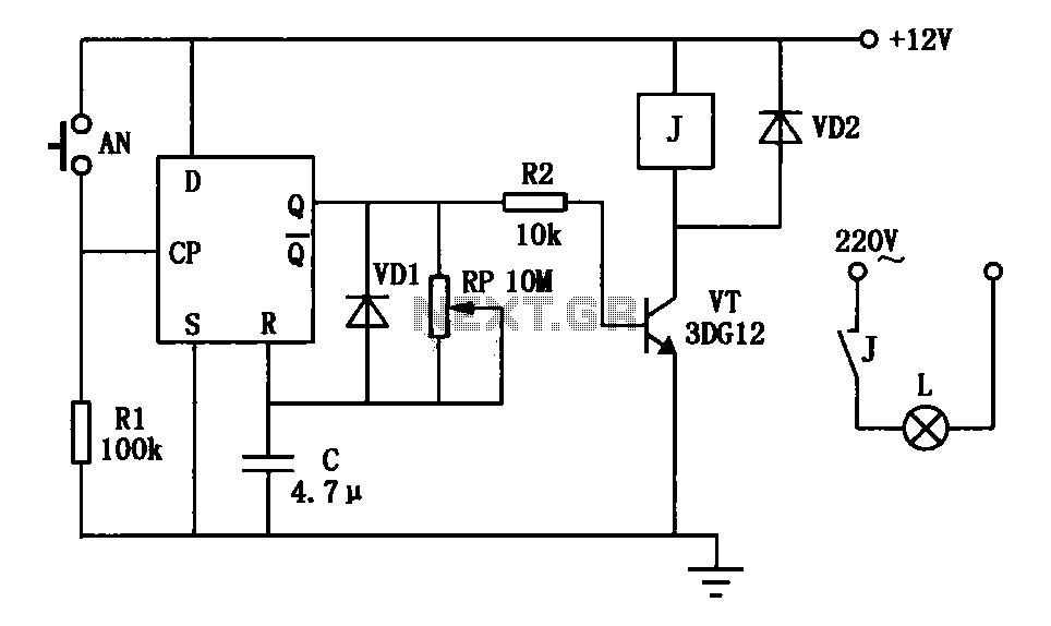
An exposure timer circuit is illustrated using D flip-flops, allowing for timing adjustments between 1 to 30 seconds. The D flip-flop circuit is connected to a one-shot timer. When exposure is required, pressing button AN generates a pulse that...
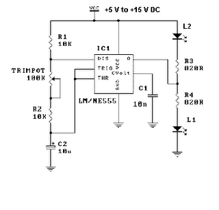
This is a simple LED flasher project that utilizes a common 555 timer integrated circuit (IC) for its operation. It is configured in astable mode, which means its output functions as a square wave oscillator. Two LEDs are connected...
A PIR sensor is triggered when using a timer to wait for 2 seconds after the sensor is activated. Without the timer, the sensor operates as intended. The PIR sensor is connected to an ATMega328p microcontroller, which has three...
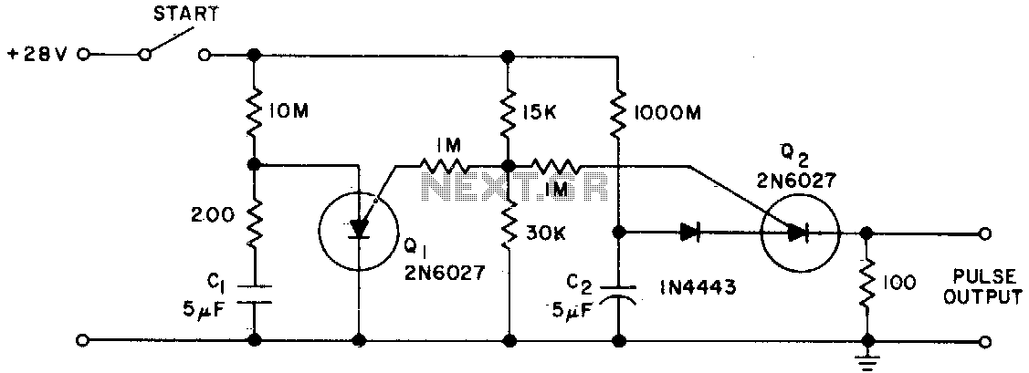
The Programmable Unijunction Transistor (PUT) serves as both a timing element and a sampling oscillator. A low leakage film capacitor is required for capacitor C2 because of the minimal current supplied to it. The Programmable Unijunction Transistor (PUT) is a...
Pulse width modulation (PWM) is a technique to control analog circuits with a digital output. PWM is used in many applications, especially to control light intensity and speed on motors. A PWM circuit makes a square wave with a...
Warning: include(partials/cookie-banner.php): Failed to open stream: Permission denied in /var/www/html/nextgr/view-circuit.php on line 713
Warning: include(): Failed opening 'partials/cookie-banner.php' for inclusion (include_path='.:/usr/share/php') in /var/www/html/nextgr/view-circuit.php on line 713