
Touch Sensitive Musical Bell With Timer PCB

The circuit operates by utilizing a touch-sensitive mechanism that activates the melody generator upon contact. The touch plates serve as input sensors, which detect the bridging of the plates by a conductive object, such as a human finger. When the plates are touched, a signal is sent to the CD4011, a quad 2-input NAND gate CMOS IC, which processes the input and sends a trigger to the UM66 melody generator.
The UM66 is specifically designed to produce various melodies, making it suitable for applications such as doorbells or alert systems. The automatic shutoff feature is implemented through a timer circuit, which can be configured using additional components, such as resistors and capacitors, to determine the duration of the music playback. This feature enhances user experience by preventing continuous sound output and conserving power.
Powering the circuit requires careful consideration of voltage levels. The UM66 operates optimally at a lower voltage, necessitating the use of the 1N4148 diodes to ensure that the voltage supplied to it does not exceed its maximum rating. The diodes introduce a forward voltage drop, allowing the circuit to function correctly within the specified voltage limits. The 7805 voltage regulator is a crucial component that provides a stable 5V output, ensuring consistent operation of the entire circuit.
Overall, this touch-sensitive musical bell circuit combines simple yet effective components to create an engaging and functional electronic device. The design is suitable for hobbyists and professionals looking to implement a straightforward musical alert system with automatic features.This circuit diagram is a UM66 based touch sensitive musical bell. The circuit is built around CMOS IC CD4011 and popular melody generator IC UM66. The circuit contains a pair of touch plates. When these are bridged by hand for a moment, the um66 starts making music. Moreover this circuit has a timer which stops the music automatically after a few seconds. This makes the circuit, an automatic music bell. The maximum supply voltage for this circuit is 5Volts dc. However the um66 can not operate beyond 3. 3V. So three diodes 1N4148 are connected series to power the music IC UM66 because of the drop of approximately 1. 8 volts across them. You should use a voltage regulator 7805 to power this circuit. 🔗 External reference
Related Circuits
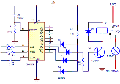
This electronic timer switch will turn on a light for 100 seconds, turn it off for another 100 seconds, and then turn it on again for 100 seconds after an hour of powering up the circuit. It is a...
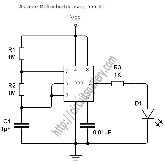
An astable multivibrator can be designed using a 555 timer IC, operational amplifiers, or transistors. The 555 timer IC provides accurate time delays ranging from milliseconds to hours, with the frequency of oscillation adjustable through simple modifications. This is...

The team is highly interested in the design of a jammer circuit and has begun working on it. However, they are experiencing issues with the circuit, specifically that the signal is not being jammed effectively. The design of a jammer...
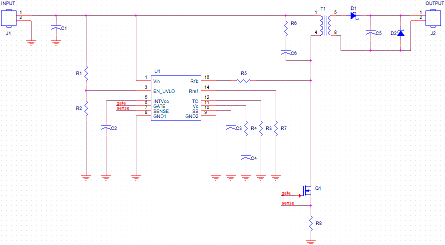
The schematic is created using OrCAD Capture and is derived directly from the datasheet of the flyback controller LT3748. This project involves constructing a custom transformer. Due to the unavailability of the desired bobbin, the transformer will be placed...

The circuit of an active shortwave antenna enhances weak shortwave signals, allowing for improved clarity when received by a shortwave receiver. The receiver does not need a physical connection; it can be placed within 6 to 7 cm of...

In this circuit, the alarm activates under four different conditions: 1. When light falls on LDR1 (located at the entrance). 2. When light on LDR2 is obstructed. 3. When door switches are opened or a wire is cut. 4....