
Regulated Positive Voltage Booster
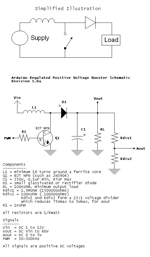
The circuit described operates on the principles of PWM control and inductive energy storage, utilizing a transistor switch (Q1) to modulate the current flowing through an inductor (L1). The inductor serves as an energy storage element, allowing for the regulation of output voltage based on the duty cycle of the PWM signal. The transistor operates in a switching mode, where it alternately allows current to flow through the inductor and then interrupts that flow, causing the inductor to release its stored energy and maintain the output voltage.
In this design, it is crucial to select an appropriate inductor, as its inductance value will influence the circuit's response to PWM signals and the efficiency of energy transfer. The inductor must be constructed with insulated wire to prevent short circuits, and its physical dimensions should be adequate to handle the expected current levels without overheating.
The Arduino ATMega168 plays a pivotal role in monitoring and adjusting the output voltage based on feedback from the circuit. By employing an analog-to-digital converter (ADC), the microcontroller can continuously assess the output voltage and modify the PWM duty cycle to maintain a stable output, accommodating variations in load. This feedback loop enhances the circuit's performance and reliability, ensuring that the output voltage remains within desired parameters.
In summary, the design leverages the properties of inductive components and PWM control to achieve efficient voltage regulation, with careful consideration given to component selection, circuit topology, and feedback mechanisms for optimal performance.When Q1 is active, a larger current begins to flow through L1 to GND. When Q1 is switched off, the current through L1 trys to remain the same as it was, causing an increased voltage. By varying the PWM duty cycle, the current through L1 and output voltage can be controlled. There are many ways to explain the relationship between PWM (analog output) and output voltage. The simplest way to put it, is that as PWM duty cycle increases, the voltage also increases. This is true when the output load remains constant. What the PWM does is control power, and if output current remains constant, then the voltage increases (P=VI). Alternately, at any given PWM if the output current is reduced, the voltage will increase. Without regulation, the output voltage would change as the load changed. Don`t worry about the gain of the transistor. (I`ve tested 2N3904, 2N2222, 2N4124, etc. ) Connecting it correctly, is all that`s important. When the circuit is powered by batteries or the Arduino, the gain of the transistor will have little effect on ouput power.
Also note that even though the transistor is rated for 30Vdc (in most cases), it should be safe to use up to 60Vdc for two reasons. 5V logic on the transistor base doesn`t saturate it, so the voltage drop across the transistor is generally less than 1/2 the circuit output voltage.
The second reason is that the voltage rises when the transistor is off and not conducting. By the time the transistor is turned back on, the voltage should have dropped back down closer to the input voltage. This is why most 30V NPNs can handle generating 60V. The exact inductance of L1 doesn`t matter. The circuit is capable of using almost any inductor. Any insulated wire wrapped at least 16 times around metal should work, regardless of the wire`s guage (thickness).
I don`t even own an inductance meter, and this is the first time I`ve used inductors in a project. I randomly wrapped wire around metal, and had a working inductor on my third try. It`s easy, my advice is don`t let it intimidate you. Just remember the important parts: insulated wire (not bare wire) wrapped tight around a smooth metal object (sharp edges could cut the insulation), and wrap the wire around the metal more than a dozen times. Take a look at the pictures below, try making your first inductor about the same size as them. If you`re trying to get more than one watt, then use a darlington pair. With BJT power transistors, the most you`ll get is about 4 watts, efficiently. With N-Channel power MOSFETs, it`s possible to get 25 watts at about 70% efficiency with a good power inductor (it`s very difficult).
To get past 30 watts, you`ll lose efficiency, need a different frequency PWM, or an elaborate/expensive switch. The Arduino ATMega168 regulates the output voltage. Regulation is important when the output load varys. The software senses changes in the output voltage, and adjusts the PWM to compensate. The output voltage depends on load and input voltage, which are "unknown" variables, so the mathematical relationship between PWM duty cycle and output voltage are "guessed" by the program.
If the input voltage and output load were constant, the Arduino analog input wouldn`t be necessary. Because of regulation, almost any load and input voltage can be used to make an accurate output voltage. Each inductor behaved a bit differently. The ones with thick wire didn`t regulate well, and the barrel/can shaped inductors in the top row generally wouldn`t go above 24V.
The top two inductors were hand made, but didn`t work. The washer had sharp edges that probably scratched enamel off the wire, shorting it. The screw just doesn`t have enough turns. Connect ADC pin 0 to circuit Aout, which is between the 1. 5M and 100K resistors shown in the schematic. Make sure ADC pin 0 is connected correctly, or your output voltage wont be regulated. 🔗 External reference
Related Circuits
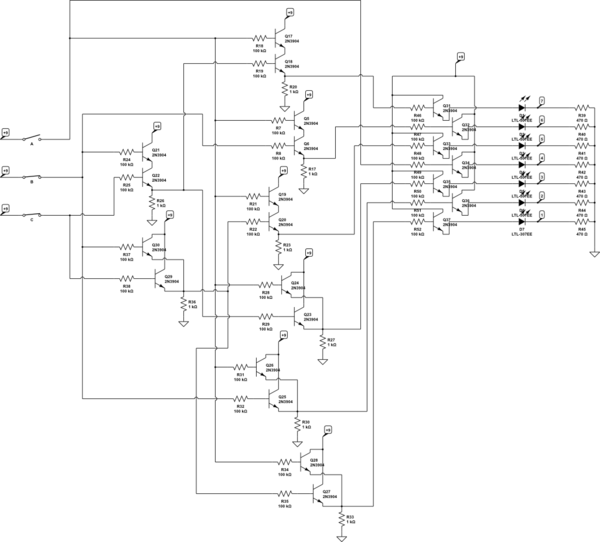
There are three switches that represent a binary number, and according to the combination of those switches, the number of lit LEDs changes to represent that binary number. There is a question regarding how to provide equal current and...
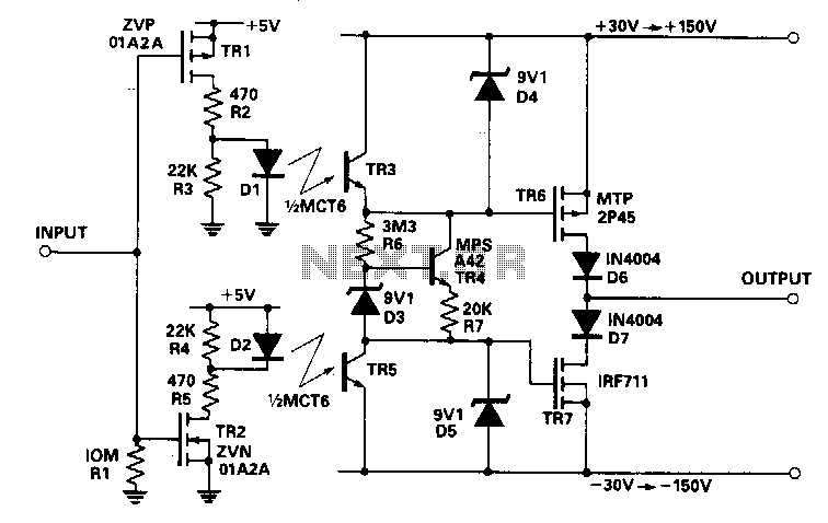
This circuit accepts a signal from a 5-V CMOS logic circuit and produces a high voltage of the same polarity. The high-voltage supply can be adjusted between ±30 V and ±150 V without requiring any changes to the circuit...
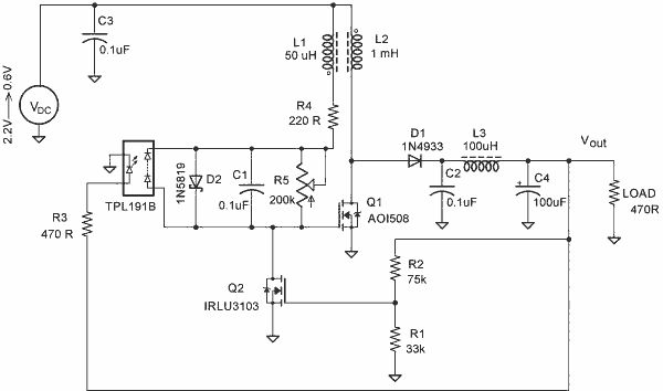
A simple blocking oscillator circuit can be utilized to increase voltage by leveraging the properties of coil inductance (V = L di/dt). Such a circuit is illustrated in Figure 1. The blocking oscillator circuit is a type of oscillator that...
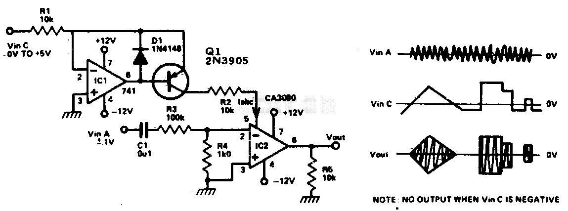
This circuit is essentially an operational amplifier (op-amp) with a differential input voltage of ±10 mV between pins 2 and 3, along with an additional input at pin 5. A current (Iabc) is injected to control the current at...
The fixed voltage power supply is useful in applications where an adjustable output is not required. This supply is simple, but very flexible as the voltage it outputs is dependent only on the regulator and transformer you choose. The...
The LM3361A features a complete narrowband FM demodulation system that operates at supply voltages of less than 2V. The device includes several blocks such as an oscillator mixer, FM IF limiting amplifier, FM demodulator operational amplifier, scan control, and...