
Relay Computer Two
The relay computer design emphasizes the use of relays as fundamental components for logical operations and data processing. Each relay serves as a switch that can either connect or disconnect circuits, facilitating the execution of instructions defined in the custom instruction set architecture (ISA). The ISA is structured into four primary categories, allowing for organized and efficient command execution. The Branch category enables conditional operations, guiding the flow of the program based on specific criteria. Data Movement instructions facilitate the transfer of information between registers and the data bus, while ALU Function instructions handle arithmetic and logical operations essential for computation.
The floating zero concept is crucial to the system's reliability and functionality. By ensuring that the zero state does not connect to any power source, the risk of short circuits is minimized, particularly during state transitions in the relays. This design choice enhances the stability of the memory registers and overall operation of the relay computer. The electrical latching mechanism employed in the registers ensures that once a value is loaded, it remains stored until explicitly changed. This approach allows for efficient data retention and retrieval, essential for program execution.
In terms of physical construction, the relay computer's layout must be carefully planned to accommodate the 281 relays and associated circuitry. The arrangement should facilitate easy access for maintenance and troubleshooting, while also ensuring that signal integrity is maintained throughout the system. The wiring must be organized to prevent interference and ensure that each relay operates correctly within its designated function.
Overall, the relay computer project represents a blend of creativity and technical understanding, resulting in a unique computing device that showcases the principles of relay logic and custom instruction sets. The endeavor not only serves as an educational experience in computer architecture but also pays homage to the foundational concepts of early computing systems.The simple relay adder was built using free NOS relays sometime in 2005, but my goal was to someday build a more elaborate one that could run programs but notfill up a room like the early computers. Harry Porter built an incredible 415-relay computer which can be seen at this page: I never thought I`d fully understand how his computer worked, let
alone build one. Finally in spring 2007, I gained more understanding of computer systems from a course in college then joked to a friend about using the x86 instruction set for a relay computer to boot up Windows, which would`ve taken several hundred years on a relay computer running on a 50Hz clock. And so the inspiration began. (note: if you want to skip the hardware details of the computer, the pictures and videos are at the end of this page).
Seriously, the x86 instruction set is insanely large for a simple relay computer so I created my own instruction set. I looked at Harry Porter`s relay computer design for inspiration and ideas for the hardware. But first, the computer cannot exist without the actual relays. After searching several online electronics suppliers for relays, the lowest price I could find was at $1 per relay so a computer using 200+ relays can become rather expensive.
So ebay was the next option and after patiently watching several auctions, a lot of 168 SPDT relays came up and I nabbed it for about $25. A few weeks later, another lot of 100 4PDT relays came up and I won it for about $14. Including shipping costs, the total cost for the 268 relays I purchased from ebay was about $60. So, 268 relays became my limit for the computer design. Obviously, I did not try to copy Harry Porter`s relay computer because it called for 400+ relays, but I borrowed many ideas from his design so I wouldn`t have to reinvent the wheel.
During the weekends at school, the relay computer was designed with a limit of 268 relays (which eventually increased to 281 relays), a 8-bit data bus, a 16-bit address width, and a floating zero. Moreover, I created my own instruction set architecture (ISA) using only 5-bit instructions for simplicity.
One might wonder "what the heck is a floating zero " There is a significant difference between using a grounded zero compared to a floating zero in relay logic. The grounded zero means the zero is represented by a connection to the power supply ground. This can simplify certain logics such as the XOR, which would need only one relay. My first relay adder used the grounded zero. However, the grounded zero poses problems with other logics such as the memory registers due to the potential of shorting out the power supply.
I circumvented this problem in my first relay adder by using resistors. A floating zero basically means there is no connection to the power supply ground, positive source, or anything, hence the name "floating" zero. This is hugely beneficial for avoiding shorts when the relays change states, especially in the registers.
Before continuing to the details of the relay CPU hardware, the hardware is based on the instruction set architecture (ISA) chosen. My ISA is basically classified in four different categories: Branch, Data Movement, ALU Function, and Halt and the exact instructions and definitions may be viewed here: Relay Computer Two ISA.
The register works based on electrical latching. When the HOLD line is high then if the memory relay coil is activated, the switch closes and keeps the coil activated. When the HOLD line is turned off, that is, disconnected from the positive supply source, then the coil is unable to remain energized and the switch opens.
So to load from the data bus, the LOAD input is set high and the relay disconnects the HOLD line from the positive source, thereby al 🔗 External reference
Related Circuits
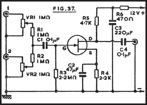
It is often convenient to fade in or out or mix the inputs from two audio sources at any desired level. The circuit depicted is suitable for this purpose. One input connects to socket 1, and the second to...
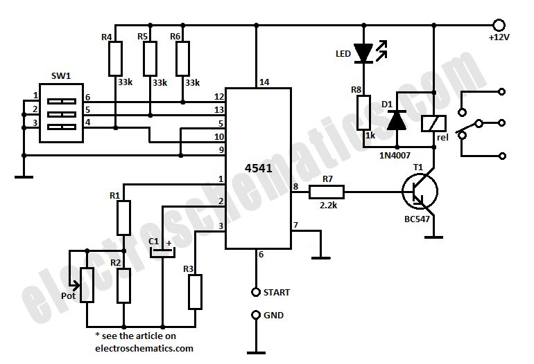
To initiate the timing process, there are two options available: either connect the START point to ground (GND), in which case the timer activates when connected to the voltage supply, or employ a switch to start the timer. The timing...
This circuit allows a 12v relay to operate on a 6v or 9v supply. Most 12v relays need about 12v to "pull-in" but will "hold" on about 6v. The 220u charges via the 2k2 and bottom diode. When an...
In his circuit Marin has used two transistors wired as a high gain compound pair. Transistor T1 may be a 2N2222A and T2 a BC108. The current gain will be the product of each transistors beta, which will be...
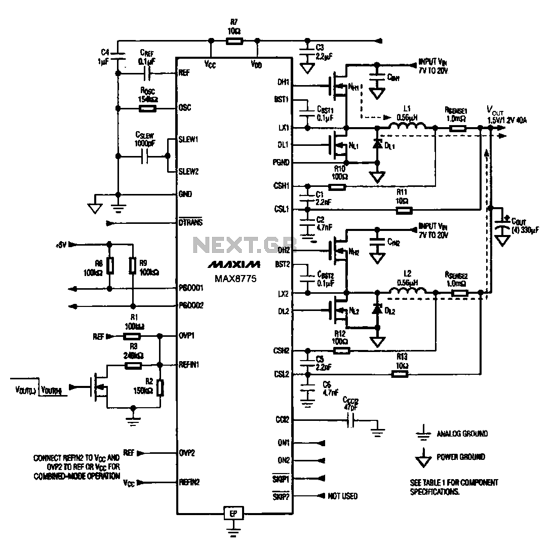
Notebook computer chip power supply circuit, which generates the PWM circuit using MAX8775. The notebook computer chip power supply circuit utilizes the MAX8775 integrated circuit to generate a Pulse Width Modulation (PWM) signal. The MAX8775 is a high-efficiency step-down voltage...
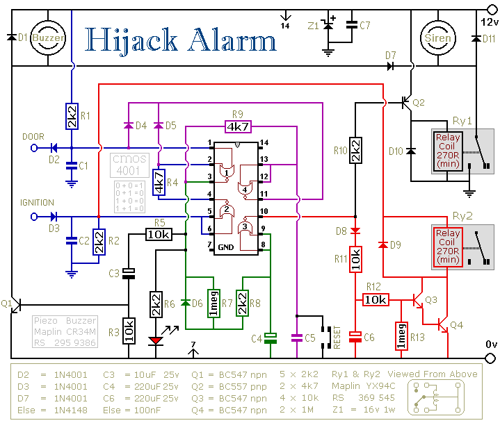
The first circuit was designed for the situation where a hijacker forces the driver from the vehicle. If a door is opened while the ignition is switched on - the circuit will trip. After a few minutes delay -...