
Water Activated Relay
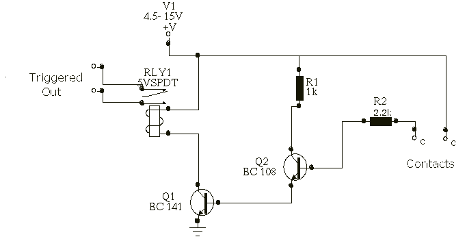
The circuit described utilizes a high-gain compound pair configuration consisting of two bipolar junction transistors (BJTs), specifically the 2N2222A and BC108. The 2N2222A serves as the first transistor (T1), while the BC108 functions as the second transistor (T2). This arrangement is designed to amplify weak signals, with the overall current gain being the product of the current gains (beta) of the two transistors, which are specified to be at least 140 for T1 and 110 for T2. This results in a theoretical maximum current gain of 15,400, providing a significant amplification factor that is advantageous for various applications.
The circuit operates within a power supply voltage range of 4.5 to 15 volts, making it versatile for different electronic applications. The relay used in the circuit is a typical 5-volt relay, which requires a current of 60 mA to activate. The relay's activation is contingent upon detecting a minimum current of 4 microamperes (uA) flowing through the sensing medium, which can be achieved using conductive fluids such as tap water or rainwater. This feature allows the circuit to function effectively as a fluid sensor, where the presence of water completes the circuit and energizes the relay.
In practical implementation, the transistors should be appropriately biased to ensure they operate within their active regions. Proper heat dissipation measures should also be considered, especially for the 2N2222A, as it may generate heat under load conditions. The circuit can be further enhanced with additional components such as resistors for biasing, capacitors for stability, and diodes for flyback protection in relay applications. Overall, this configuration provides a robust solution for fluid detection and control applications, leveraging the high gain characteristics of the transistor pair.In his circuit Marin has used two transistors wired as a high gain compound pair. Transistor T1 may be a 2N2222A and T2 a BC108. The current gain will be the product of each transistors beta, which will be a minimum of 140 x 110 or 15400. The power supply used can be any voltage from 4.5 to 15 volts, a typical 5 volt relay may require 60 mA to operate, in which case any fluid which passes a minimum current of 4 uA will activate the relay.
This is easily achieved with tap or rain water. 🔗 External reference
Related Circuits

This small water sensor alarm circuit produces a loud warning sound when a humidity sensor detects the presence of water. The circuit utilizes the low-power comparator LM1801 from National Semiconductor. The reference voltage for the integrated circuit is established...
This project involves the construction of a relay driver suitable for both DC and AC relays. Since DC and AC voltages operate differently, the setups for their respective relay drivers require slight variations. A generic relay driver that can...
After experiencing equipment failure, a decision was made to replace a combination inverter/charger unit with individual components that fulfill the same requirements. The combination unit, referred to as the "Everything Box," is an efficient solution for cost savings by...
This simple circuit illustrated in the schematic diagram activates the switch using sound. It can be utilized for various applications, such as automatic (sound-controlled) disco lights or car LED light shows. The transistor Q1 amplifies the audio from the...
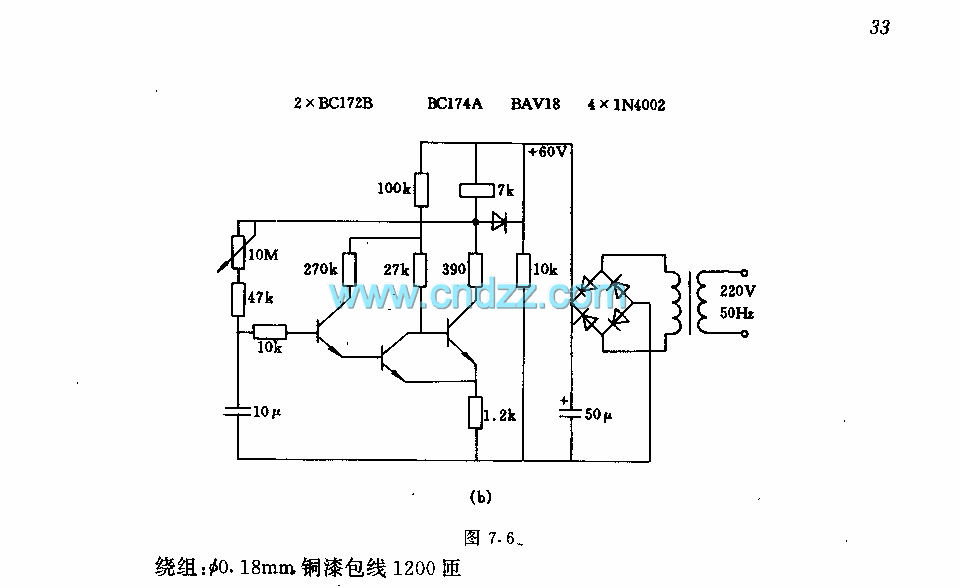
The circuit features a two-stage structure with a timing range of approximately 0.5 to 12 seconds, while in a specified configuration, the timing range extends from 1 to 160 seconds. The transformer parameters include an iron core made of...
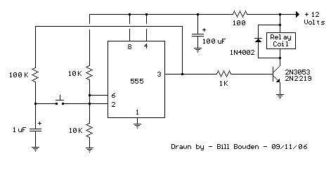
This 555 timer circuit activates a relay upon pressing a button. The threshold and trigger inputs, pins 2 and 6, are maintained at half the supply voltage by two 10K resistors. When the output is high, a capacitor charges...