
relay triac
The conversion from a relay to a triac in this design presents a viable option for controlling a nichrome wire heater operating at 120V with a resistance of 60 ohms. Triacs are advantageous for AC control applications due to their ability to switch and control power in both directions of the AC cycle.
In Method 1, the circuit design involves integrating a transistor (T1) to control the gate of the triac. The neutral of the 120V AC line is connected to the circuit ground, allowing for a common reference point. The resistor connected to the gate of the triac is crucial for limiting the current and ensuring proper triggering of the triac. The nichrome wire is connected in series with the triac, enabling the triac to control the power delivered to the nichrome wire directly. The collector of T1, connected to the +12V supply, allows for a low-voltage control signal to manage the higher voltage triac operation.
In Method 2, the design opts for electrical isolation between the control and power circuits. By utilizing an opto-isolator, the control signal from T1 can safely operate the triac without a direct electrical connection to the high-voltage side. This method enhances safety and reduces the risk of noise interference from the high-voltage circuit affecting the control logic. The opto-isolator transmits the control signal via a light beam, providing a reliable way to trigger the triac while maintaining separation from the primary circuitry.
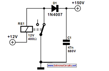
Both methods require careful consideration of component ratings, particularly the triac, which must be capable of handling the 120V AC voltage and the current flowing through the nichrome wire. Additionally, thermal management should be addressed, as both the triac and the nichrome wire will generate heat during operation. Proper heat sinks and thermal interfaces may be necessary to ensure reliable operation and longevity of the components. Overall, transitioning from a relay to a triac can enhance the efficiency and responsiveness of the heating circuit while maintaining safety and operational integrity.How hard it would be to convert the relay in this design to a triac It switches a 120v Ni-chrome wire that is 60ohms. Thanks for any help you can offer. Your right i apologize. The ic powers off of a 12v transformer. However there is a 120v neutral and line onboard that feeds a 12v voltage reg ulator. Here is the proposed circuit. It`s still a work in progress. Method 1) Connect the 120 volt neutral to the circuit ground, then use T1 to send current through a resistor to the gate of a triac and connect one end of the nichrome to the 120 circuit and the other end to the anode of the triac. The third terminal of the triac goes to ground. The collector of T1 goes to the +12 supply. method 2) Don`t connect the 120 neutral to the circuit ground. Have T1 drive an opto-isolator and have that drives a triac. The nichrome power circuit will stand seperate from your primary circuitry, connected only by a light beam inside the opto-isolator.
🔗 External reference
Related Circuits
A practical and engaging project involving a flip-flop relay circuit utilizing a 555 integrated circuit (IC). This circuit will continuously toggle two relays on and off in succession. The flip-flop relay circuit using a 555 IC is designed to alternate...
A circuit is needed to control a couple of large AC solenoid valves and several single-phase AC motors. The line voltage is 132VAC, with the solenoids drawing 1A and the motors drawing 13A and 27A when operating. The goal...
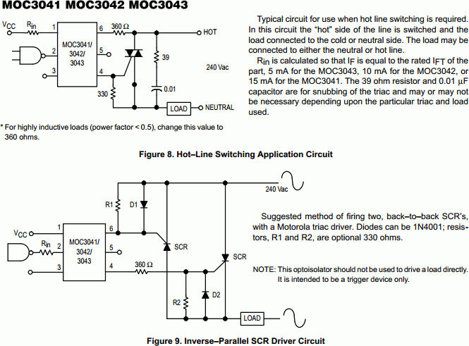
The MOC303XM and MOC304XM devices consist of an AlGaAs infrared emitting diode optically coupled to a monolithic silicon detector, functioning as a zero voltage crossing bilateral triac driver. They are designed for use with a triac in the interface...
Switched mode power supply units (SMPSUs) are popular but difficult to build oneself as well problematic when it comes to understanding their design principles. Switched mode power supply units (SMPSUs) are widely utilized in various electronic applications due to their...
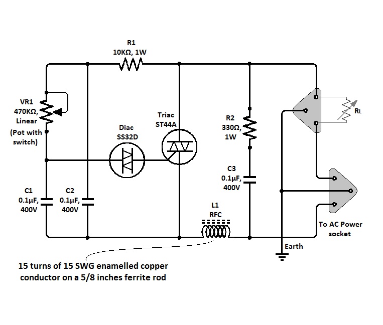
The circuit of a simple triac light dimmer can be used to dim incandescent lamps directly from AC mains. It is easy to construct and requires very few components. A potentiometer is utilized to control the load power or...
A clock-controlled relay, also known as a time delay relay, allows for the automatic activation of a load, such as a water pump, at a predetermined time. This device utilizes a standard clock mechanism to trigger the circuit, enabling...