
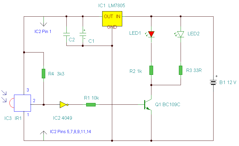
Remote Alarm For Smoke Detector

This alarm circuit is engineered to ensure the safety of a shed environment, specifically designed for dog kennels. The system is integrated with a mains-powered smoke detector, which serves as the primary sensor for smoke detection within the shed. The circuit provides complete electrical isolation, which is crucial for preventing any interference from other electrical devices within the shed, thereby ensuring reliable operation of the smoke detector.
The circuit typically includes a power supply section that converts mains voltage to a lower, safe operating voltage for the alarm system. This section may utilize a transformer or a switch-mode power supply for efficiency.
The smoke detector is connected to the alarm circuit through an isolation mechanism, such as an opto-isolator, which ensures that any potential faults do not affect the mains power supply. When smoke is detected, the smoke detector sends a signal to the alarm circuit, triggering an audible alarm or visual indicator, such as a flashing LED.
Additional features may include a reset mechanism, allowing the user to silence the alarm after the smoke has cleared, and a test button to regularly check the functionality of the smoke detector and alarm system. The circuit may also incorporate a battery backup to maintain operation during power outages, ensuring continuous monitoring.
Overall, this alarm circuit is a critical component in maintaining safety within the shed, providing peace of mind to the owners of the dog kennels by ensuring that any smoke is detected promptly.This alarm circuit was designed to monitor a mains-powered smoke detector located in a shed (which is used to house dog kennels). It provides complete iso.. 🔗 External reference
Related Circuits

This compact design forms a remotely operated switch that receives its control signal via the mains voltage. The switch is operated using the mains remote transmitter described elsewhere in this issue. With this transmitter, a switch should be connected...
This is an improved IR remote control extender circuit. It has high noise immunity, is resistant to ambient and reflected light and has an increased range from remote control to the extender circuit of about 7 meters. It should...

Figure (a) illustrates an infrared emission circuit composed of a 12-key keyboard and an S2559. Figure (b) displays a DTMF decoder circuit along with a channel control circuit utilizing the MT8870. Figure (c) presents a voltage amplifier circuit constructed...

A simple transistor-based motorcycle alarm circuit. This circuit is easy to build and designed to operate at 12 volts. However, by replacing the relay with one that has a 6-volt coil, it can also provide protection at that voltage. The...

The DS1307 is a hardware real-time clock that operates using the I2C protocol. It features improved graphics with a traditional alphanumeric LCD (model HD44780). Icons indicate the status of the Alarm ON/OFF state, enhancing the visual appeal of the...

This simple circuit uses an incandescent lamp to detect airflow. With the filament exposed to air, a constant current source is used to slightly heat the filament. As it is heated, the resistance increases. As air flows over the...