
Remote-Control Analyzer Circuit
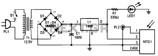
The remote analyzer circuit provides a straightforward yet effective means of analyzing infrared signals. The power supply section begins with a transformer that converts the AC mains voltage to a lower AC voltage, suitable for the needs of the circuit. The 12.6-V transformer is connected to a bridge rectifier made up of four diodes (D1 to D4), which converts the AC voltage to pulsating DC. The capacitor (CI) smooths out the ripples in the rectified output, providing a more stable DC voltage to the subsequent components.
The 7805 voltage regulator (Ul) is a crucial component that ensures the output voltage remains at a constant 5 V, regardless of variations in input voltage or load conditions. This regulated voltage is essential for the proper functioning of the infrared detector module (MODI).
The GPIU52X infrared detector module is designed to demodulate signals at a frequency of 40 kHz, which is a common carrier frequency for infrared remote controls. This functionality allows the circuit to effectively capture and analyze infrared signals transmitted from remote control devices. The demodulated output, which consists of logic pulses representing the transmitted signal, is then routed to an oscilloscope through the BNC connector (PL2). This allows for visual analysis of the signal waveform, facilitating troubleshooting and verification of remote control operations.
LED1 serves as a visual indicator of the circuit's operational status, providing immediate feedback to the user when the circuit is powered on. The inclusion of the optional switch (SI) allows for convenient control of the circuit's power without the need to disconnect the power supply. Overall, this schematic diagram illustrates a well-designed circuit for analyzing infrared remote control signals, combining essential components for power regulation, signal demodulation, and user feedback. A schematic diagram for the remote analyzer is shown. The circuit is powered from a simple 5-V supply, consisting of PL1, SI, Tl, a bridge rectifier (comprised of D1 through D4), capacitor CI, and a common 5-V regulator, Ul. Switch SI is the on/off control and is optional. The power-supply transformer used in the prototype is a 12.6-Vac unit, but any transformer that can supply at least 5.6-Vac will do.
The 12.6-V unit was used solely because of its availability. The output of Tl is full-wave rectified by diodes D1 through D4 and filtered by CI. The bumpy dc output from the capacitor is regulated down to 5 V by Ul, a 7805 integrated regulator. LED1 acts as a power indicator to let you know that the circuit is active. The 5-Vdc powers a GPIU52X infrared-detector module* (MODI), which demodulates the 40-kHz carrier used by most infrared remotes. After demodulation, the resulting logic pulses are sent to an oscilloscope via PL2, a BNC connector. 🔗 External reference
Related Circuits
One of the major problems that must be addressed in electronic circuit design is the generation of low voltage DC power supply from mains power to energize the circuit. In electronic circuit design, the conversion of mains AC voltage to...
This is a follow-up to an earlier post regarding a specific circuit schematic. The circuit is designed to operate at a supply voltage of 5V, and testing has confirmed that the original device functions correctly at this voltage. A...
The circuit is designed for high precision operation over an extended temperature range, provided that V+ remains relatively constant, as the current IZ is dependent on V+. Resistors R1, R2, R3, and R4 are selected to ensure the appropriate...
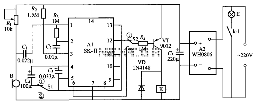
The circuit consists of an acoustic sensor, SK voice circuit, relay control circuit, vocal music circuit, and an AC buck rectifier circuit. The described circuit integrates several key components, each serving a distinct function to achieve the desired operational characteristics....
The PIC16C57-RCT is a communication single-chip microcomputer integrated circuit that is commonly utilized in the Qiao Xing series of IC card management telephones. The PIC16C57-RC integrated circuit features a pulse and dual-tone dialing circuit, memory data and clock circuit,...
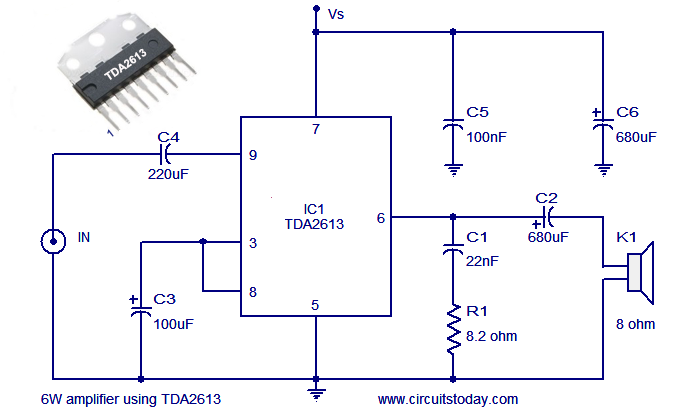
A simple and easy-to-build Hi-Fi audio power amplifier circuit is presented here. This 6-watt Hi-Fi audio amplifier circuit utilizes the TDA2613 integrated circuit (IC). The circuit design employs the TDA2613, which is a high-performance audio amplifier IC known for its efficiency...