
UM91214B IC For Radio Remote Control

The Radio Remote Control Circuit utilizing the UM91214B IC is designed to facilitate wireless control applications. This integrated circuit is particularly adept at processing DTMF signals, which are commonly used in telecommunications to convey information through audio signals. The circuit typically includes a transmitter and a receiver module, allowing for bidirectional communication.
The transmitter section of the circuit includes a keypad or a DTMF generator that produces dual-tone signals corresponding to specific keys pressed. These signals are modulated and transmitted via a radio frequency (RF) module. The RF module converts the electrical signals into radio waves, which can travel over distances without the need for physical connections.
On the receiving end, the circuit employs a compatible RF receiver module that demodulates the incoming radio signals back into electrical signals. The UM91214B IC processes these signals, decoding the DTMF tones to determine which command has been sent. The output of the IC can then be used to control various devices, such as motors, lights, or other electronic components, depending on the application.
Power supply considerations for the circuit must also be addressed, typically involving the use of a regulated power source to ensure stable operation of both the transmitter and receiver. Additionally, the circuit may incorporate various passive components, such as resistors and capacitors, to filter signals and stabilize the operation of the IC.
Overall, this Radio Remote Control Circuit using the UM91214B provides an efficient and reliable method for wireless control, leveraging DTMF technology to enable versatile applications in remote operation scenarios.The following circuit shows a Radio Remote Control Circuit Diagram. This circuit based on the? UM91214B IC. Features: use of DTMF (dual-tone . 🔗 External reference
Related Circuits
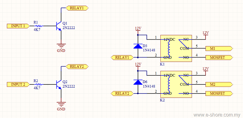
The circuit utilizes two sets of relays for each motor to switch the motor's direction, and one set of MOSFETs for each motor to control the motor's speed. The MOSFET and relay circuit will be divided into three parts...
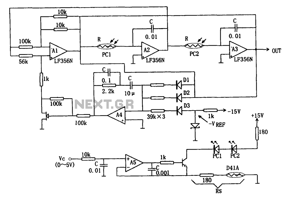
The wideband sinusoidal voltage-controlled oscillator circuit is designed such that the oscillation frequency is determined by an integrating resistor R and a capacitor C. The voltage-controlled oscillator is constituted by the applied control voltage Vc and a control resistor...
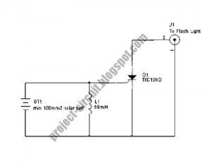
The following circuit illustrates a Slave Flash Light Control Circuit Diagram. Features include a 68mH inductor that provides an automatic trigger for the secondary flash light. The Slave Flash Light Control Circuit is designed to manage the operation of a...
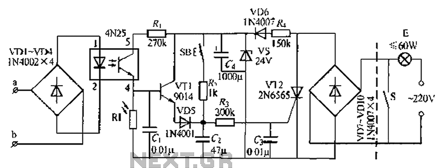
An automatic light system is integrated with a telephone block system. When the phone rings, the owner is prompted to pick up the handset or pull a lever, causing the lamp to light up. If there is no contact...
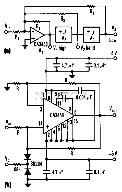
The control voltage Vc effectively adjusts the cutoff frequency w0 of this state-variable filter to any desired value, ranging from approximately 1.7 MHz to 5 MHz, using a BB 204 varicap and a resistance of 100 kΩ. Vc can...
This unit provides 2-way IR communications using a numeric keypad and an LCD display. Data is sent and received in ASCII with no regard to what the data means to any particular device. The ASCII data still needs some...