
Remote Control Operator

The problem is this: when people go way on holiday they often connect ordinary lights directly to time switches to turn the lights on and off at certain times. This gives the impression that the house is still occupied, but it can also come in useful when visitors, who stay till the small hours of the night, need a little hint that it`s time to go!
But when these lights are controlled wirelessly it is unfortunately no longer possible to switch them on and off with a time switch. The light switches work with a signal that is transmitted via radio or infrared by the remote control handset.
And herein lies the problem: who controls the remote control in your absence You can`t expect your neighbours to do this for you, even if you get on very well with them. Fortunately, with a little inventiveness and some electronics we can get round this problem. With this circuit we can add electronic switches in parallel with the buttons in the remote control. Of course your remote control has to be suitable for this modification. This will be covered in detail later, in the section Modifying the remote control . To keep things simple, we have catered for a maximum of four lights. The remote control unit we bought had one on-switch and one off-switch for each light. For four lights we therefore need to control eight switches externally. The receivers are turned on by closing the four on` contacts equentially, with a short pause in between.
They are turned off again by closing the four off` contacts sequentially, with a short pause in between. As you can see from Figure 1, this time we found a solution without the use of a microcontroller. It does mean that a fair number of components are used in the circuit, but they are all without exception easily obtainable and inexpensive.
In the original design we wanted to control this circuit via an ordinary switch or the switch inside a time switch. This means that we would first have to open up the time switch to disconnect the internal microswitch from the mains.
Apart from the fact that this involves a lot of tinkering, it is not always possible. We would also have to make sure that all safety regulations were adhered to! It is much simpler to control the circuit with a voltage and use a separate mains adapter; you probably have one left over from an old mobile phone or other device (5 V to 9 V DC). This also keeps everything safe, since the adapter simply plugs into the time switch! You then set the time switch to the required times when the lights should go on and off, and the mains adapter provides a control signal to the circuit.
For other (low voltage) applications the facility is still there to control the circuit with a switch. This should be connected to JP2. In this case you should remember to put a jumper onto JP1. The switch or adapter puts a logic high level at the input of NAND IC2a. The combination of C3/R2 and C2/R4 feed a positive or negative edge to monostable multivibrator IC1a every time the input level changes.
The RC network of R3 and C4 keeps the Q output of IC1a (pin 6) high for long enough for NAND-gate IC2b to generate four pulses. The length of these four pulses determines how long the contacts of the switches in the remote control are closed and it depends on the values of R5/C5.
At the same time, the preset input of the 4-bit down-counter (IC3) receives a preset pulse from the Q output. During the time that the Q output is high, IC3 receives four pulses and then stops until the state of the input to the circuit changes.
The logic level on pin 3 of IC2a determines which part of analogue switch IC4 is active. In this way only the first four switches are active when there is a low level at pin 9 of this analogue switch, whereas the last four switches are active when there is a high level at pin 9. The enable input (pin 6) of IC4 is active low and is made high for a short period by NAND IC2b. This ensures that there are distinct gaps between each of the (electronic) key presses. Due to the tolerances of the RC networks it is possible for the last switch to be pressed twice. In principle this doesn`t really matter, since turning a light on twice still leaves it on! If you find this a problem, you can fix it by reducing the RC time of IC1a a little bit by lowering the value of R3.
To keep the circuit as compact as possible we`ve used an external mains adapter rated at 12 V AC or 15 V DC, which connects to K2. For completeness there is also a 12 V output via K1 (pin 1 is ground and pin 2 is +12 V), which can be used to supply the remote control unit.
In this case you must make sure that the batteries are removed before you connect the circuit! If your remote control doesn`t work at 12 V, then all you need to do is to replace IC6 with one that outputs the correct voltage. As we mentioned earlier, this circuit was designed for use with a specific type of remote control. This circuit will only work with types where one side of the switches is connected to one common track (and the other side of the switches is connected to separate parts of the circuit).
If your remote control unit is the same, you should solder eight plus one wires for the switches and two wires for the supply to connector K4. Then solder the wires to the contacts of the switches. Before connecting this to the circuit you should test that you soldered all wires correctly to the remote control.
Short pin 3 (M) of K4 with one of the other pins (1a to 4b) of K4. The remote control should then function just as if you pressed the corresponding key. If it all went satisfactorily you can connect K4 to K1. Don`t forget to remove the battery if you use the circuit to provide a power supply to the remote control! The construction shouldn`t give rise to any problems. In any case, always start with the wire links (including those underneath the ICs). During the design we had a particular enclosure in mind (see parts list). If you 10/2005 - elektor electronics 57 use the same enclosure you should mount the voltage regulators as close to the board as possible, in order to keep the height to a minimum.
It may help if you change the mounting holes to an oval shape with the help of a 1 mm drill. Ccontrol! 🔗 External reference
Related Circuits
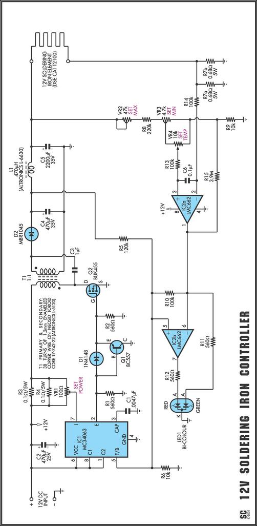
One reason commercial soldering stations are costly is that they typically require soldering irons with built-in temperature sensors, such as thermocouples. This circuit removes the necessity for a specialized sensor by detecting the temperature of a soldering iron heating...
The receiver circuit and display module will receive the high-frequency AC power cord and decode it to provide actual temperature readings using digital IC No. CD4553 (Three-digit BCD Counter IC) and IC CD4511 (BCD-to-7-Segment Latch/Decoder/Driver IC). The frequency pulses...
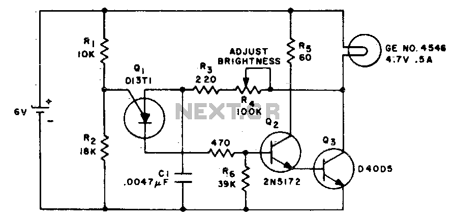
This circuit alters the average value of the DC supply voltage due to the high switching frequency. The tungsten lamp will exhibit an almost continuous adjustable light output ranging from 0 to 100%. If a light-emitting diode is utilized...
Reversing the DC power connections on a motor causes its shaft to rotate in the opposite direction. One method to control the direction is by using switches arranged in a specific configuration known as an H-Bridge. For instance, when...
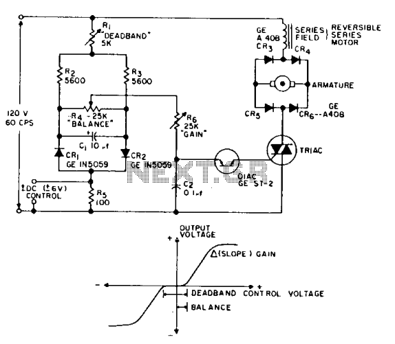
This is a positioning servo drive that includes adjustments for balance, gain, and deadband. In addition to receiving control from a DC signal, a mechanical input can be utilized for the balance control. Alternatively, this balance control can be...
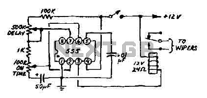
This 12V wiper speed controller circuit utilizes a 555 timer. It is a straightforward and practical circuit that can be installed in any car. The 12V wiper speed controller circuit is designed to regulate the speed of windshield wipers in...