
Car Wiper-Speed Controller
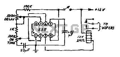
The 12V wiper speed controller circuit is designed to regulate the speed of windshield wipers in automotive applications. At its core, the circuit employs the versatile 555 timer IC, which is configured in astable or monostable mode, depending on the desired functionality. The astable configuration allows for continuous operation, while the monostable mode can provide a single pulse output for specific wiper functions.
The circuit typically consists of a few essential components: the 555 timer IC, resistors, capacitors, and a transistor for driving the wiper motor. The resistors and capacitors determine the frequency and duty cycle of the output signal, which in turn controls the speed of the wiper motor. By adjusting the resistor values or using a potentiometer, the user can vary the speed of the wipers to suit different weather conditions.
Powering the circuit with a 12V supply, which is common in automotive systems, ensures compatibility with most vehicle electrical systems. The output from the 555 timer is connected to the base of a transistor, which acts as a switch to control the current flowing to the wiper motor. This arrangement allows for efficient control over the motor's speed without excessive power loss.
In addition to its simplicity, the circuit can be easily integrated into various car models, making it a versatile solution for enhancing wiper functionality. The design can also be modified to include additional features, such as an adjustable delay or multiple speed settings, by incorporating additional components or modifying the existing configuration. Overall, this 12V wiper speed controller circuit represents a practical and effective approach to improving vehicle wiper performance.This 12V wiper speed controller circuit uses the 555 timer. Its one of those very easy and usefull circuits! And can be fitted to any car. 🔗 External reference
Related Circuits
The schematic below illustrates 4 methods of controlling a relay with a digital logic signal. Figure (A) can probably be used in most cases where the relay coil requires 100 mA or less and the input current is 2...
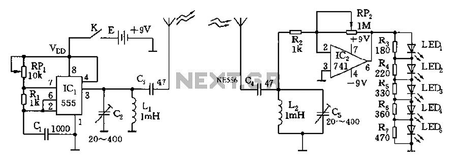
The circuit diagram of the device features a 555 timer IC configured as a transmitter and a receiver, divided into two sections. The 555 timer in the transmitter section serves as the core component of a frequency oscillator. The...
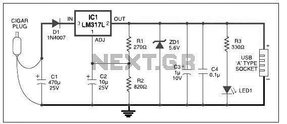
This USB car charger circuit adapter is designed for use with a car's cigarette lighter socket. It functions as a DC-DC power converter, effectively converting the 12V voltage from the car battery into a stable 5V output. This circuit...
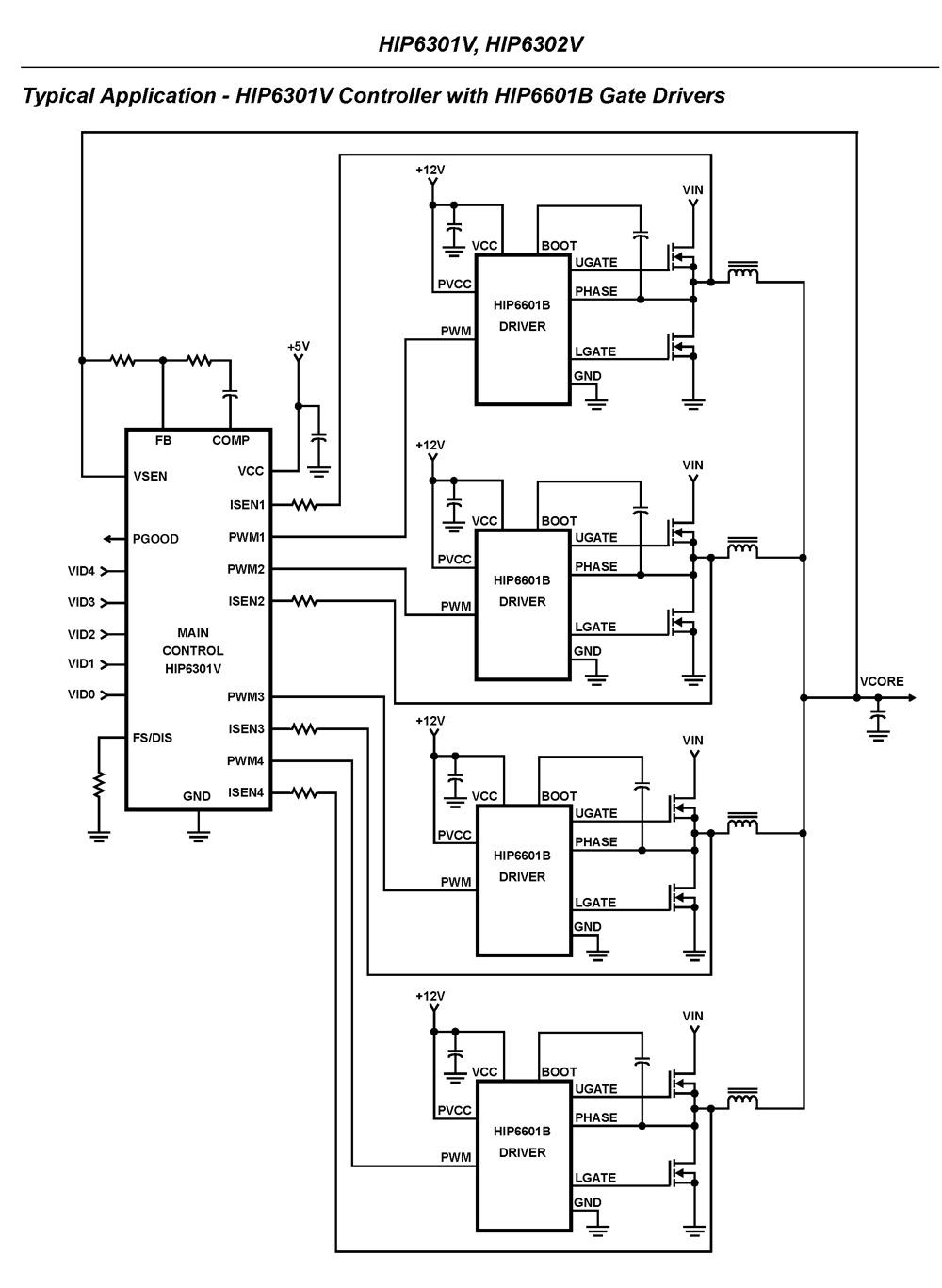
The HIP6301V and HIP6302V control the microprocessor core voltage regulation by driving up to four synchronous-rectified buck channels in parallel. The multiphase buck converter architecture employs interleaved timing to increase ripple frequency and minimize input and output ripple currents....
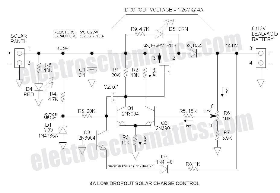
This Low Dropout Voltage (LDO) solar charge controller employs a differential amplifier and a series P-channel MOSFET linear regulator, which work exceptionally well together. The output voltage is adjustable and primarily designed for charging 12V lead-acid batteries. The input...

The trembler (motion-activated) switch triggers an alarm for 5 seconds before automatically turning off. The circuit has a timeout period of 10 seconds to allow the trembler switch to stabilize. The trembler switch circuit operates by detecting motion through a...