
Remote Control Server RCS

The proposed circuit design for remotely powering servers incorporates a microcontroller (PIC16F628) interfaced with an RS232 communication protocol, facilitating control over multiple devices. The microcontroller's architecture allows for the management of up to five independent relays, each corresponding to a server. The RS232 interface serves as a reliable communication channel between the microcontroller and the Remote Control Server application, which operates on a Windows platform utilizing Visual Basic 6.
The circuit can be powered through a universal power supply, ensuring compatibility with various PC or server configurations. The application developed in VB6 features a user-friendly interface that allows for real-time control of each relay. The configuration window enables users to customize button labels and operational modes, which can be set to either "Momentary" or "Latched." In "Momentary" mode, the relay remains active only while the button is pressed, providing temporary control. Conversely, "Latched" mode permits toggling the relay state with each button press, enhancing operational flexibility.
The application’s design includes a registry-saving feature that retains user settings, streamlining the user experience. The ability to apply changes without saving them allows for temporary adjustments without permanent alterations to the configuration. The implementation of a visual representation of the button state enhances user interaction by providing immediate feedback regarding the status of each relay.
Overall, this circuit design and application provide an efficient solution for remote server management, combining advanced microcontroller capabilities with a straightforward user interface for effective control and monitoring.One of my friends asked me if I could design a circuit for him to be able to remotely power up a server. He has 2 servers and he didn`t want to keep them both on whilst he travelled. He wanted to be able to turn on a server when he needed it. He has one server which is on all the time (web server) to which he RDPs occasionally. The project involve d a microcontroller circuit with RS232 interface and a simple application to send messages to it in real time. Since the MCU has multiple I/O pins it would be a waste to control only one server, so I have designed this project to control up to 5 servers/devices.
I have thought about getting power from PCI socket but opted against it as the motherboard slots change very often. This way you can use this card in any PC or Server. I have chosen to use PIC16F628 for the project as it is the first one to introduce an internal oscillator.
This saves cost as there is no need for crystal or caps. The Remote Control Server application is written in VB6. It sends real time button state messages to the MCU over a standard RS232 serial port (USB to RS232 cable can also be used if your laptop or PC has no serial ports). By default the application will open up in Mini mode (second picture above). All the settings are saved in the registry so you don`t need to configure the settings every time you run it up.
The names for the buttons are configurable in the Configuration window. By clicking the labels "Momentary" or "Latched" will toggle between the two modes of operation. By pressing "Cancel" button on configuration screen will apply the changes but will not save them in registry so next time you start the application it will revert to last saved settings. Application is designed to reflect the current state of the button. In "Momentary" mode if the button is held down the corresponding relay is ON, when the button is released the corresponding relay is OFF.
In "Latched" mode if the button is pressed down the corresponding relay is toggled between ON and OFF state. The button caption will reflect the current relay state ON or OFF. 🔗 External reference
Related Circuits
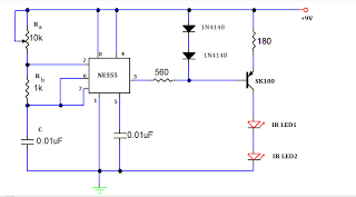
A TV remote jammer circuit using the NE555 timer IC. This device allows users to watch their favorite TV channels without interruptions, as it prevents others from changing the channel using a remote control when the circuit is activated....
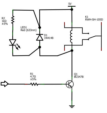
The BC547B transistor has a collector-base voltage (Vcbo) of 50V, a collector-emitter voltage (Vceo) of 45V, and an emitter-base voltage (Vebo) of 6V. In contrast, the BC548 transistor in the original circuit has a Vcbo of 30V, a Vceo...
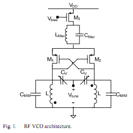
The oscillator is designed to tune from 1.8 GHz to 2 GHz for typical cellular telephony applications. An extended tuning range can be obtained by adjusting the ratio between the varactor capacitance and fixed capacitance in the tank. PMOSFETs...

The transmitter is a very simple crystal oscillator. The heart of the circuit is the tuned circuit consisting of the primary of the transformer and a 10p capacitor. These two components oscillate when a voltage is applied to them....
Utilizes a barium titanate transducer as a microphone, tuned with a 20 mH coil to generate peaks at control frequencies of 38.5 kHz and 41.5 kHz. A balanced discriminator detects the two ultrasonic tones. A frequency shift in the...
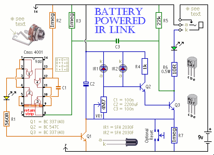
This is a battery-powered infrared (IR) link that can be utilized in multiple rooms. The standby current is exceptionally low, resulting in excellent battery life. The circuit is designed to shut down when faced with extraneous IR radiation, effectively...