
Remote-Controlled Fan Regulator
This circuit is designed for remote control of fan speed, leveraging infrared technology to provide convenience and ease of use. The TSOP1738 infrared receiver is crucial for detecting signals from a standard remote control, while the step-down transformer ensures that the circuit operates safely at a lower voltage. The full-wave rectifier and voltage regulator ensure that the circuit receives a stable power supply, which is essential for reliable operation.
The NE555 timer IC is a versatile component used in various applications, and in this circuit, it serves as a monostable multivibrator to generate a timed output pulse. The combination of the NE555 timer and the decade counter CD4017 allows for the creation of a speed control mechanism that can vary the fan's speed based on the duration of the received pulses.
The use of an optocoupler as a zero-crossing detector is particularly beneficial in AC applications, as it allows for safe interfacing between the low-voltage control circuit and the high-voltage AC load. This isolation protects sensitive components from high voltage spikes and noise, enhancing the circuit's robustness.
The triac BT136 is selected for its capability to handle AC loads, and the snubber network ensures that voltage spikes do not damage the triac during operation. The design's flexibility allows for various fan speed settings, making this circuit suitable for different applications where fan speed control is desired.
Overall, this circuit exemplifies practical applications of timers, counters, and optoisolators in creating a user-friendly system for controlling electrical devices from a distance. Proper assembly on a PCB and housing in an appropriate case are essential for achieving optimal performance and ensuring safety during operation.Using this circuit, you can change the speed of the fan from your couch or bed. Infrared receiver module TSOP1738 is used to receive the infrared signal transmitted by remote control. The circuit is powered by regulated 9V. The AC mains is stepped down by transformer X1 to deliver a secondary output of 12V-0-12V. The transformer output is rectifie d by full-wave rectifier comprising diodes D1 and D2, filtered by capacitor C9 and regulated by 7809 regulator to provide 9V regulated output. Any button on the remote can be used for controlling the speed of the fan. Pulses from the IR receiver module are applied as a trigger signal to timer NE555 (IC1) via LED1 and resistor R4.
IC1 is wired as a monostable multivibrator to delay the clock given to decade counter-cum-driver IC CD4017 (IC2). Out of the ten outputs of decade counter IC2 (Q0 through Q9), only five (Q0 through Q4) are used to control the fan.
Q5 output is not used, while Q6 output is used to reset the counter. Another NE555 timer (IC3) is also wired as a monostable multivibrator. Combination of one of the resistors R5 through R9 and capacitor C5 controls the pulse width. The output from IC CD4017 (IC2) is applied to resistors R5 through R9. If Q0 is high capacitor C5 is charged through resistor R5, if Q1 is high capacitor C5 is charged through resistor R6, and so on. Optocoupler MCT2E (IC5) is wired as a zero-crossing detector that supplies trigger pulses to monostable multivibrator IC3 during zero crossing.
Opto-isolator MOC3021 (IC4) drives triac BT136. Resistor R13 (47-ohm) and capacitor C7 (0. 01 µF) combination is used as snubber network for triac1 (BT136). As the width of the pulse decreases, firing angle of the triac increases and speed of the fan also increases. Thus the speed of the fan increases when we press any button on the remote control. Assemble the circuit on a general-purpose PCB and house it in a small case such that the infrared sensor can easily receive the signal from the remote transmitter.
🔗 External reference
Related Circuits
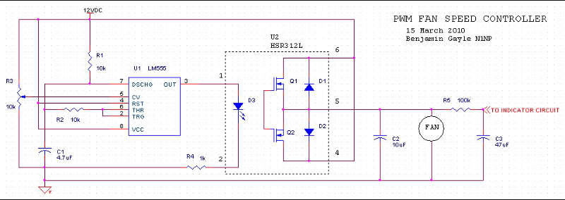
A fan speed controller for computer fans consists of two sections: one for manual speed control and another for automatic temperature-dependent speed control. Additionally, there is a section for a simple LED output indicator. While it is common to...
This is a simple circuit of a low-power voltage regulator reference. This circuit can produce a stable voltage reference. The low-power voltage regulator reference circuit is designed to provide a consistent output voltage, which is crucial for various electronic applications...
Precision high voltage regulator power supply. Refer to the corresponding page for an explanation of the related circuit diagram for the power supply. This simple switching regulator circuit provides a 5 V output, with the input supplied by a...
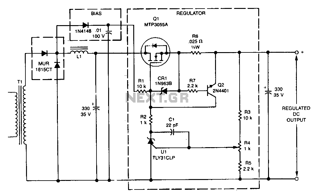
This linear post regulator provides 12 V at 3 A. It utilizes the TL431 reference (U1), which, without additional amplification, drives the gate of the TMOS MTP3055A (Q1) series pass regulator. A bias voltage is applied through resistor R1...
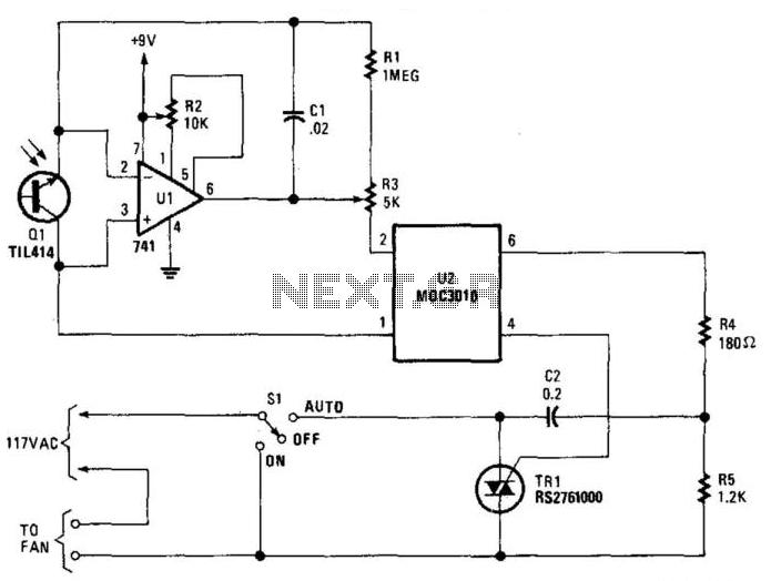
Q1 senses infrared radiation from heat sources, which causes U1 to switch on, activating optocoupler U1 and triggering TRIAC TR1. This controls a fan. The TRIAC can be sourced from Radio Shack or a 200-V, 6-A unit (C106B) can...
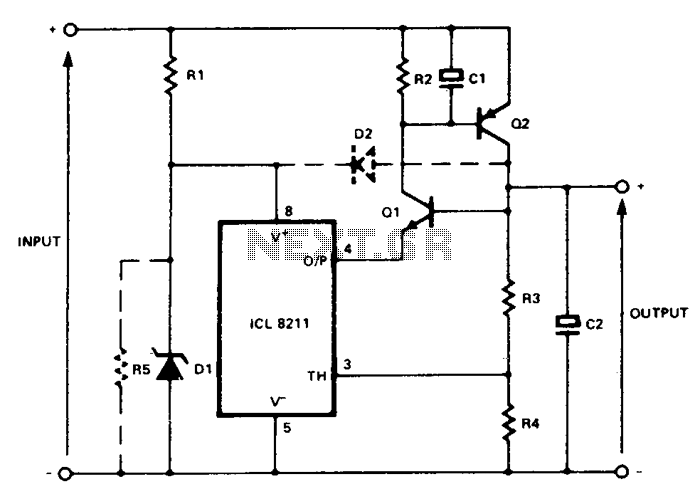
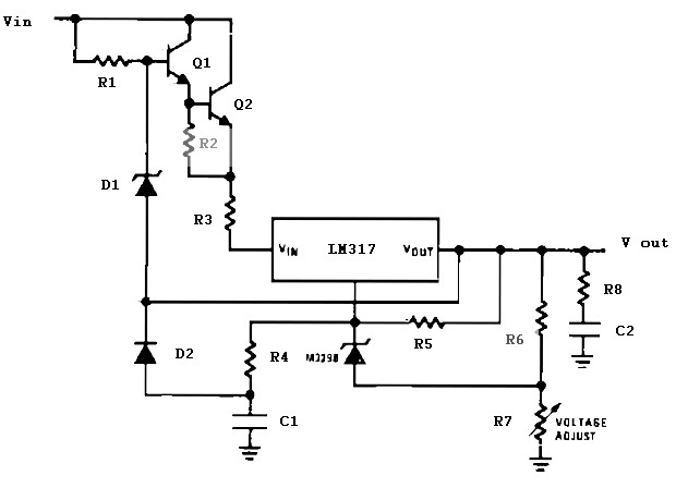
In the circuit, Q1 and Q2 are connected in the classic SCR or thyristor configuration. When higher input voltages or a minimal component count are required, the thyristor boost circuit can be utilized. The thyristor operates in a linear...
Warning: include(partials/cookie-banner.php): Failed to open stream: Permission denied in /var/www/html/nextgr/view-circuit.php on line 713
Warning: include(): Failed opening 'partials/cookie-banner.php' for inclusion (include_path='.:/usr/share/php') in /var/www/html/nextgr/view-circuit.php on line 713