
Repeating Interval Timer 2
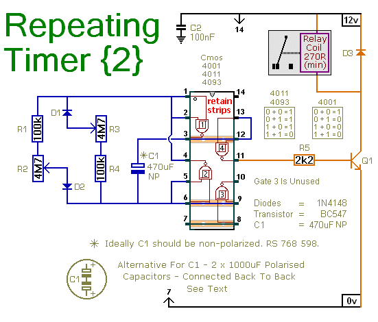
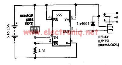
The repeating timer circuit is designed around a single CMOS integrated circuit (IC), which operates as an asymmetric oscillator. This configuration allows for independent control over two distinct timing intervals: one for the duration the relay is energized and another for the duration it is de-energized.
The circuit typically includes a few passive components such as resistors and capacitors, which are crucial for determining the oscillation frequency and duty cycle. The timing is established by the values of these components, allowing for customization based on the application requirements.
In operation, when powered, the CMOS IC generates a square wave output that alternates between high and low states. During the high state, the relay is activated, allowing current to flow through the load connected to the relay contacts. The duration of this state is controlled by the RC time constant, which is influenced by the selected resistor and capacitor values.
Once the set time elapses, the IC switches to a low state, deactivating the relay and cutting off the current to the load. The time spent in this state is also determined by the RC time constant configured for the de-energized interval.
This timer circuit can be applied in various applications, including automatic lighting systems, irrigation systems, and other scenarios where controlled on-off cycling of a device is required. The simplicity of using a single CMOS IC makes it an efficient and cost-effective solution for timer-based control systems.This is a simpler repeating timer circuit. It uses just one Cmos IC - wired as an asymmetric oscillator. The length of time the relay remains energized - and the length of time it remains de-energized - are set independently.. 🔗 External reference
Related Circuits
This is an SCR timer circuit. In this circuit, an SCR is utilized to activate the final actuator, which is a buzzer. The time constant of the circuit is determined by resistor R1 and capacitor C1. The buzzer will...
This is a programmable clock timer circuit that utilizes individual LEDs to display hours and minutes. Twelve LEDs can be arranged in a circle to represent the twelve hours of a clock face, while an additional twelve LEDs can...
The following circuit illustrates a Repeating Interval Timer Circuit Diagram. This circuit is based on the CMOS 4060 integrated circuit (IC). Features include a 6-pin output. The Repeating Interval Timer Circuit utilizing the CMOS 4060 IC is designed to generate...
The water sensor circuit utilizes a 555 timer configuration along with standard electronic components. It consists of two metal electrodes positioned closely enough that a drop of water can create a conductive bridge between them. In cases where the...
This circuit provides a visual 9-second delay using a 7-segment digital readout LED. When the switch is closed, the CD4010 up/down counter is preset to 9, and the 555 timer is disabled with the output held high. When the...
This document presents an improvised circuit model designed to eliminate unwanted DC offset voltage from the output, which affects previously discussed circuits. All prior circuits were intended as low-power Class D amplifier sources suitable for driving headphones through a...
Warning: include(partials/cookie-banner.php): Failed to open stream: Permission denied in /var/www/html/nextgr/view-circuit.php on line 713
Warning: include(): Failed opening 'partials/cookie-banner.php' for inclusion (include_path='.:/usr/share/php') in /var/www/html/nextgr/view-circuit.php on line 713