
repeating timer

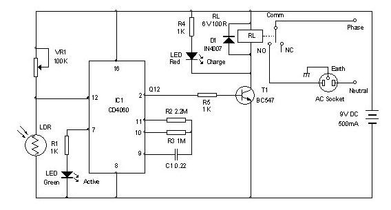
This monostable timer circuit utilizes a single trigger input to generate a precise timing interval during which the relay is activated. The timing characteristics are primarily influenced by the resistor-capacitor (RC) timing network formed by R3 and C2 for the ON period, and R4 and C3 for the OFF period. The circuit can be configured to achieve a variety of timing intervals by selecting appropriate resistor and capacitor values.
The operation of the timer begins with a trigger signal applied to the input, which causes the output to switch and energize the relay. The relay remains activated for the duration determined by the RC time constant of R3 and C2. After the ON period elapses, the relay deactivates, and the timer enters the OFF period, which is defined by the RC time constant of R4 and C3. This cycle can be repeated as needed, making the circuit suitable for various applications, such as automatic lighting control, delay circuits, or timer-based activation of devices.
The choice of components is critical for achieving the desired timing accuracy. The tolerances of the resistors and capacitors can affect the timing intervals, so it is advisable to use components with low tolerance ratings for applications requiring precise timing. The circuit's flexibility allows for customization by adjusting component values to meet specific timing needs, which can be beneficial in practical applications.
Safety considerations must be taken into account when using this timer circuit, especially when interfacing with mains voltage. The recommendation to mount the relay away from the board is essential to ensure safety and prevent potential hazards due to insufficient isolation. Proper relay selection based on the power supply voltage is also crucial to ensure reliable operation and prevent damage to the components.
In summary, this monostable timer circuit is a versatile solution for controlling relay activation periods, allowing for adjustable ON and OFF timing intervals through careful selection of resistor and capacitor values, while emphasizing safety and reliability in its design and application.This timer is based on a simple Monostable Circuit. The length of time the relay remains energized - the ON period - is controlled by the values of R3 & C2. And the length of time the relay remains de-energized - the OFF period - is controlled by the values of R4 & C3.
With the component values shown - periods of up to 30 minutes are available. Th e length of time the relay remains energized is controlled by the values of R3 & C2. And the length of the time the relay remains de-energized is controlled by the values of R4 & C3. Owing to manufacturing tolerances - the precise length of the time periods available depends on the characteristics of the actual components you`ve used. You can choose component values that suit your own requirements. You should get about 70 seconds for every 1Meg/100uF. So 4M7 & 100uF will give about 6 minutes. And 4M7 & 1000uF will give about an hour. If your time periods don`t need to be too precise - and more-or-less is close enough - you can replace the pots with fixed resistors.
Do not use the "on-board" relay to switch mains voltage. The board`s layout does not offer sufficient isolation between the relay contacts and the low-voltage components. If you want to switch mains voltage - mount a suitably rated relay somewhere safe - Away From The Board.
The timer is designed for a 12-volt power supply. However - it will work at anything from 5 to 15-volts. All you need do is select a relay to suit your supply voltage. I`ve used a SPCO/SPDT relay - but you can use a multi-pole relay if you wish. 🔗 External reference
Related Circuits
The two circuits below illustrate the application of the 555 timer to activate a relay for a specified duration by pressing a momentary normally open (N/O) push button. The circuit on the left can be used for longer time...
Timer for Charger Circuit Diagram. This timer circuit assists in maintaining the battery in optimal condition by enabling automatic charging for 5 to 6 hours daily, allowing the device to be left unattended. The timer circuit for the charger is...
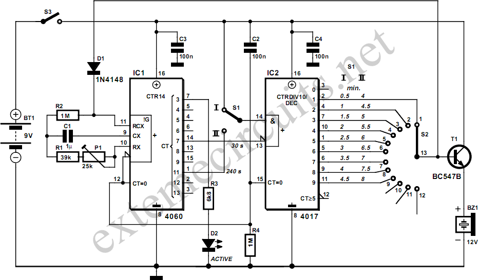
This egg timer, which is both simple and functional, demonstrates that it is not essential to use a microcontroller for everything these days. The circuit consists of only two integrated circuits (ICs) from the standard 4000 logic family, a...
The circuit is a 0-60 second timer using timer 555 and two 4017 for LED driving. The described circuit employs a 555 timer IC configured in monostable mode to create a timing interval ranging from 0 to 60 seconds. The...
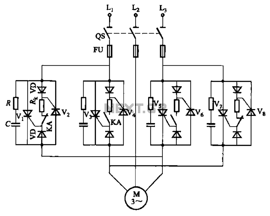
The circuit depicted in Figure 3-69 is designed for applications requiring frequent timing control for motor reversing operations. In this configuration, thyristors V1, V2, V7, and V5 are utilized for positive control of rotation, while thyristors V3, V4, and...

This circuit is a voltage-controlled oscillator (VCO) that utilizes the 555 timer integrated circuit (IC) as its primary component. The 555 timer is configured as an astable multivibrator, enabling it to function as an oscillator. An astable multivibrator is...